









BLOG
USB-C EPR Rise-Time Testing: Why Are 275ms and 700ms Limits Not Interchangeable?
QUICK LINKS
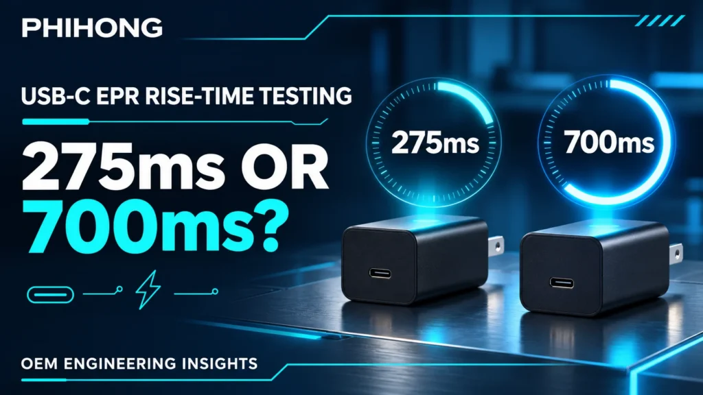
Quick answer: USB-C EPR rise-time limits are not interchangeable because the AA240U specification assigns them to different output-profile groups under a stated load condition. Use 275ms for the listed lower-voltage group and 700ms for the listed EPR group, then confirm the timing definition.
A test report can contain a precise elapsed time and still compare it with the wrong requirement. For the AA240U-59FKEA-R desktop adapter, the output-ramp entry is separate from turn-on delay and from the downstream product’s complete startup. Those clocks need distinct labels.
The goal is to agree what starts the timer, what ends it, which voltage profile is active and how the load behaves during the ramp. Without that information, arguing over a few milliseconds does not establish whether the adapter or the system meets its requirement.
Choose the limit associated with the actual voltage profile
The AA240U technical datasheet lists a rise-time maximum of 275ms for 5V, 9V, 15V and 20V. For 28V, 36V and 48V it lists 700ms. The stated condition is full load, 100Vac/60Hz, in CR mode. Preserve that complete context beside the limit. The 700ms figure is not a family-wide substitute for a lower-voltage requirement.
Verify the operating profile with the qualified USB-C test arrangement. A request shown in software is not enough if the output never established the expected operating point. Retain the relevant profile evidence and voltage trace together. If the test involves a change between profiles, confirm whether the source’s rise-time entry actually covers that event before comparing it with either number.
The broader guide to EPR voltage profiles explains why these voltage options exist. This article focuses on measurement classification. It does not infer a physical explanation for the different limits from the numbers alone or claim that every USB-C adapter uses the same timing groups.
| Output profiles | Maximum rise time | Listed test condition |
|---|---|---|
| 5V, 9V, 15V, 20V | 275ms | Full load, 100Vac/60Hz, CR |
| 28V, 36V, 48V | 700ms | Full load, 100Vac/60Hz, CR |
Why This Matters
- The correct limit depends on the actual output condition, not simply on a 240W label.
- A profile transition and an initial output ramp may require different definitions.
What OEMs Should Do Now
- Record the confirmed profile beside the result and selected maximum.
- Ask whether the specific event being measured is covered by the published rise-time entry.
FEATURED PRODUCTS
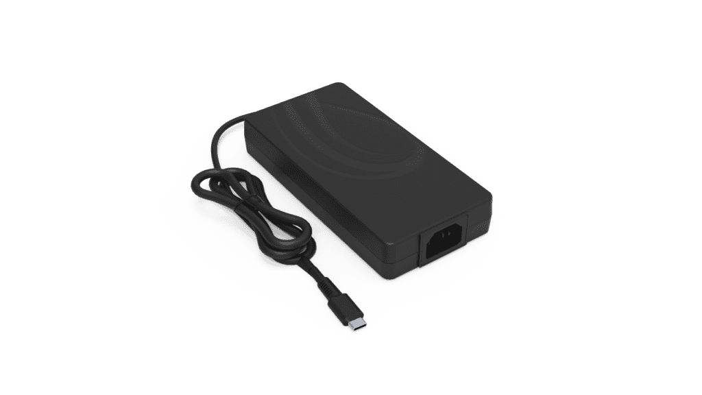
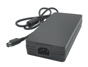
AA240U-59FKEA-R
- Output Power - 240 Watt
- Output Volt - 5Vdc/ 9Vdc/ 15Vdc/ 20Vdc/ 28V/ 36V/ 48V
Define the timing markers before collecting a pass or fail
Rise time needs a start threshold, an end threshold and a reference convention. The brief AA240U entry does not fully specify those markers. Do not import a familiar 10–90% definition from another model or instrument default and present it as this model’s published method. Confirm the intended convention before accepting or rejecting a borderline waveform.
A threshold should also name its voltage reference. A percentage of nominal output and a percentage of the captured final value are not automatically identical when the final value differs from nominal. Noise, overshoot and a temporary plateau can affect an automatic timing measurement. Keep the captured waveform and the marker placement visible so the elapsed time can be reviewed.
Agree how repeated crossings or a non-monotonic ramp will be evaluated. An automatic cursor result is useful only if its algorithm matches the approved method. If the source does not define a behavior, record the observation and ask for clarification rather than inventing an acceptance rule. This is particularly relevant when a test is being converted into a production-line check.
Why This Matters
- A precise timer cannot compensate for an undefined start or end event.
- Instrument defaults can make two laboratories report different times from the same waveform.
What OEMs Should Do Now
- Obtain the applicable threshold convention and retain it with the test procedure.
- Save the waveform with visible markers and state how the reference voltage was selected.
Keep constant-resistance loading distinct from constant-current loading
The source specifies CR, or constant-resistance, mode for this rise-time condition. Under an ideal fixed resistance, current increases as voltage rises. Under a constant-current command, the instrument attempts a different current behavior once it reaches its operating region. These modes can impose different startup demands. Substituting one without agreement changes the experiment even if both reach the same final power.
An actual receiver can behave differently again. Input capacitance, an undervoltage lockout circuit and downstream conversion can create a staged demand during startup. That behavior belongs in system validation, but it should not silently replace the CR-mode reproduction. Measure the actual low-voltage current and output ramp together when investigating the difference.
State how the full-load CR condition is implemented for the chosen profile, and confirm the load equipment’s operating limits and behavior during a low-voltage ramp. Do not infer the required resistance from the 240W maximum for every profile. The applicable profile rating and agreed method define the final operating condition. Preserve any load mode transitions visible in the trace.
| Condition | What it answers |
|---|---|
| Specified CR reproduction | Does the output ramp meet the agreed model method? |
| Constant-current experiment | How does the supply respond to that different load behavior? |
| Actual receiver startup | Does the complete device start reliably in its use case? |
Why This Matters
- Matching final watts does not make two startup load modes equivalent.
- A receiver’s input sequence can alter startup behavior without changing the adapter specification.
What OEMs Should Do Now
- Use the stated CR method for the supplier comparison and record its implementation.
- Run the real receiver separately, retaining its current demand and reset or ready events.
Separate rise time, turn-on delay and device-ready time
The AA240U datasheet lists turn-on delay separately, with a maximum of 3 seconds at full load and 100Vac/60Hz. That entry and the profile-dependent rise-time limits should remain separate in the report. Do not add them together to manufacture a new total-startup guarantee; equally, do not apply the rise-time limit to an interval that begins with a different event.
A complete product trace can include input application, USB-C activity, output establishment, receiver power sequencing and firmware readiness. The USB-C power-up and device-startup guide discusses the wider integration problem. For this AA240U test, identify which markers belong to the component method and which belong to the application. A device-ready signal is not a substitute for a voltage threshold.
If the product occasionally fails to start, preserve both successful and unsuccessful sequences using the same markers. Note profile, initial state, residual energy and load configuration as applicable. A timing difference may be an important clue without proving one particular root cause. Keep the first investigation focused on event ordering before assigning blame to the adapter or firmware.
Why This Matters
- Different startup clocks can produce an apparent failure when the wrong interval is compared.
- System readiness includes behavior beyond the adapter’s output ramp.
What OEMs Should Do Now
- Label every marker by its physical or protocol event, not a generic “startup” caption.
- Maintain separate component timing and complete-device readiness results.
How Phihong supports a clear rise-time acceptance method
For a useful AA240U-59FKEA-R review, provide the revision, voltage profile, input condition, load mode, current trace, output trace and timing markers. Ask specifically for the threshold definition and whether the captured event matches the listed rise-time test. If a profile transition or receiver behavior differs from that method, describe it as a separate application question.
The public source provides a starting point, while the project’s current agreed specification should control acceptance. Confirm availability and revision before building production limits around a public listing. Do not turn a test ambiguity into an invented universal USB-C rule. The objective is a method that both the supplier and OEM can run and interpret consistently.
Retain the agreed marker convention and representative captures in the 240W adapter validation record. Include device-ready timing when it affects the product, with its own requirement. The USB-IF Power Delivery overview is useful protocol background but does not replace the exact model’s timing definition or establish end-device compatibility.
Why This Matters
- An agreed event definition makes later incoming and qualification results comparable.
- Documenting the distinction prevents a product-ready requirement from being misrepresented as a component limit.
What OEMs Should Do Now
- Resolve threshold and event ambiguity before final pass/fail disposition.
- Keep the approved timing method and application readiness criteria together but separately labeled.
Useful Links: AA240U-59FKEA-R product details · AA240U-59FKEA-R technical datasheet
Related Links: 240W EPR test-correlation guide · Ripple probe setup · Surge capture and averages · 28V, 36V and 48V profiles · Power-up versus device startup · 240W production validation
Frequently Asked Questions
Can I use 700ms for a 20V output?
Not as a substitute for the listed AA240U condition. Its 20V profile is in the 275ms maximum group under the stated full-load CR test condition.
Does the brief entry define a 10–90% measurement?
It does not fully specify that threshold convention. Confirm the intended markers with Phihong instead of borrowing a definition from another model or the instrument default.
Is rise time the same as USB-C negotiation time?
No. They describe different events. Confirm which event the component entry covers and retain protocol and voltage timing as separately labeled observations.
Why does CR mode matter during a ramp?
A fixed-resistance load draws current according to the rising voltage. Constant-current loading and a real receiver can present different demand patterns, so matching final power alone is insufficient.
What if the adapter ramp passes but the product starts late?
Evaluate the complete receiver sequence, including downstream rails and firmware readiness. A component timing pass does not establish a device-ready deadline or diagnose the cause of a system delay.