









BLOG
Medical Accessory Startup: Why Can a Device Reset When Its Display or Radio Turns On?
QUICK LINKS

An accessory can complete boot and then reset when its screen lights or its radio connects. The visible symptom may look like firmware instability. It can also follow a brief voltage dip at the accessory’s input or a downstream rail. The quickest way to distinguish those cases is to align the electrical signals with the exact transition.
Quick answer. Record adapter output, accessory input, current and a reset or state marker in the same acquisition. Compare the timing during a reproducible display or radio event before assigning a cause.
Why This Topic Matters Now
A firmware update can change which functions start together. A service cable can add enough resistance for a previously acceptable event to become intermittent. Those changes can arrive independently and create a symptom that appears only in certain units. Record the original configuration before swapping parts.
| Capture first | Why it matters |
|---|---|
| Adapter and cable part numbers | Identifies the power path that produced the symptom |
| Accessory and firmware revision | Connects the symptom to the real startup sequence |
| Battery condition | Explains potential differences in device input behavior |
| Exact action that triggers reset | Makes repeatable comparisons possible |
Which signals separate the failure paths?
Measure source output and voltage where the accessory receives power. Add current and a firmware marker or reset indication where the test design allows. If the application supports logs, compare their event timing with the measured trace. A log entry can stop before the real electrical symptom is visible, so keep both forms of evidence.
| Observation | Next check |
|---|---|
| Source steady, device input dips | Cable and contact path, including the return |
| Source and device input dip together | Source behavior, current event and upstream interruption |
| Device input stable, internal rail dips | Downstream power conversion and sequencing |
| Electrical rails steady, reset repeats | Watchdog, firmware state and event logs |
Use measurement equipment appropriate to the accessory and the qualified lab procedure. Identify the probe points in the test record. A trace labeled only “5V” can hide whether it was measured upstream or downstream of the cable and connector.
How do you isolate display, radio and charging events?
Reproduce the original sequence several times and identify the interval that coincides with reset. Where the product team permits a controlled diagnostic build, run display and radio events individually, then run them together. If battery charging is part of the load, repeat with relevant approved battery states. Compare traces while changing one variable at a time.
A transient can be brief but meaningful if it crosses a threshold for long enough to trigger a reset. Conversely, a measured dip that occurs after a firmware reset may be an effect of the changed load state. Timing helps distinguish these cases. Preserve the time axis and trigger point with the annotated capture.
When should the OEM compare another cable or source?
Compare the original cable with a known-good approved cable first. Keep the source, device and sequence unchanged. If the accessory voltage improves with the comparison cable while source voltage stays steady, investigate the cable and contact path. If both ends sag together, compare the measured load event with source behavior and the exact model documentation.
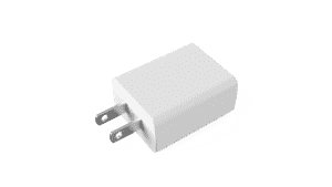
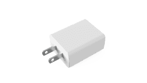
Phihong lists the MQ05A-050BW-H at 5V and 1A. The datasheet describes the model’s published ratings and test setup. A nominal rating by itself does not establish what occurred in the accessory during the fault, and a successful test with another source does not by itself qualify that source for production or service.
How should the fix be verified?
Repeat the original failing test after the change, then check startup, wake, simultaneous operating states and recovery across the supported combinations. Verify product behavior as well as the waveform. Where the fix is sequencing, identify the firmware revision and verify that timing still meets the design requirement. Where the fix is a cable change, update the approved parts and service documentation.
| Release item | Evidence |
|---|---|
| Original failure | Trace with current, voltage and event timing |
| Corrected configuration | Exact parts and firmware revision |
| Regression results | Original sequence and supported operating conditions |
| Service information | Symptoms, approved parts and escalation criteria |
Key Takeaways
Investigate a reset as a timed event across the source, cable and device. Keep the original configuration and change one variable per comparison. Validate the correction in the released accessory and capture the evidence that service teams can reuse.
FAQs
Can the source be within rating while the accessory resets?
Yes. Device-side voltage and downstream rail behavior can differ from what is seen at the adapter.
Does the first visible symptom identify the cause?
No. Use a synchronized trace to determine what changes before the reset and what changes afterward.
Can a software workaround close the issue?
Only after the approved team verifies the electrical behavior and intended operation of the corrected configuration.
Discuss your design with Phihong. Review the medical usb power product family or contact Phihong with the model, operating conditions and qualification question.