

BLOG
How Do OEMs Manage EMI/EMC and Safety Challenges in DC/DC Converter Design?
QUICK LINKS
Why do EMI and EMC issues commonly arise in DC/DC converter designs?
EMI (electromagnetic interference) and EMC (electromagnetic compatibility) challenges are inherent to DC/DC converter design because switching power supplies operate by rapidly turning currents on and off at high frequencies. These fast switching edges generate conducted and radiated noise that can easily propagate through power lines, ground planes, cables, and enclosures. In industrial, medical, and automation environments, this noise can disrupt nearby electronics, interfere with communication protocols, or cause products to fail regulatory testing.
OEMs often encounter EMI/EMC problems late in development when devices move from controlled lab conditions into real enclosures with cables, connectors, motors, or external sensors. What appears stable on a bench can quickly become unstable when long cable runs act as antennas or when multiple converters interact on a shared power bus. Poor PCB layout, insufficient filtering, improper grounding, or underestimating switching harmonics are common root causes.
In addition to functional issues, EMI failures can block global market access. Regulatory bodies require compliance with standards such as CISPR, EN, FCC, and IEC limits before products can ship. Addressing EMI early in the DC/DC converter design process is therefore not just a technical concern but a commercial necessity for OEMs building scalable, globally deployable products.
Top Benefits
-
Reduces risk of EMI-related certification failures
-
Prevents interference with sensors, communication, and control logic
-
Improves overall system stability in noisy environments
Best Practices
-
Identify switching frequencies and harmonic ranges early
-
Minimize high-di/dt and high-dv/dt loop areas in PCB layout
-
Use proper input and output filtering near the converter
Managing EMI proactively allows OEMs to avoid late-stage redesigns, protect system performance, and ensure products pass compliance testing without delays.
(Suggested Links: Internal Power Supply Guide | Innovations in Medical Power Design)
FEATURED PRODUCTS
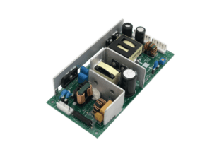
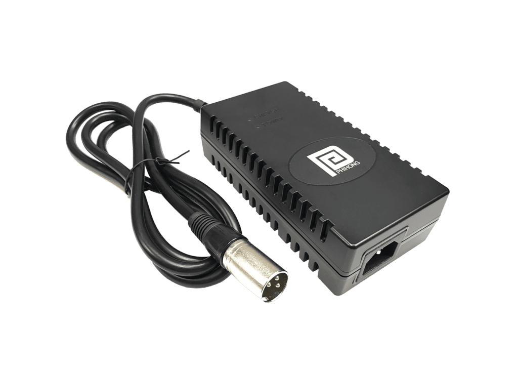
AA03A-075A-R
- Output Power - 2.75W
- Output Volt - 7.5V
- Output Current - 0.366A
- Features - Fixed Blade AC Input, Limited Power Source, Class B EMI, Level VI Efficiency, Standard Barrel Connector

AC Series
- Output Current - 16A
- Features - Mode 2-chargers can use a circuit ranging from 8Amp to 16Amp with a local standard AC input plug installed for operation, Provides overcurrent, over voltage and short circuit protection, Protected against strong jets of water from all directions, Continuously monitors/supervises the ground connection between the AC supply and EV to ensure safe and reliable charging
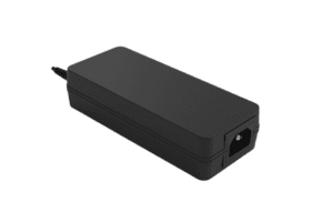
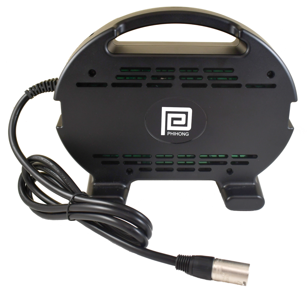
BF550-234A-R
- Output Power - 550W
- Output Volt - 12Vdc / 54.5Vdc
- Features - Universal AC Input range, Class I Design , Class B EMI , High Efficiency Performance , OVP, OCP, SCP, OTP Protections , Operating Altitude: 5,000M
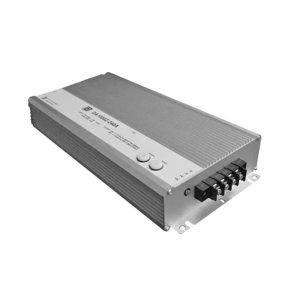
DA1000Z-240AEV-R
- Output Power - 1000W
- Output Volt - 24V
- Output Current - 1000W
- Features - Extended operating temperature range of -40℃ to 70℃, Fan-less aluminum case filled with heat conductive glue, Able to withstand 10G vibration, Power on LED indicator, Short Circuit, Over Current, Over Voltage, and Over Temperature Protections, & Adjustable output through potentiomete
DA60U-240A-R
- Output Power - 60W
- Output Volt - 24V
- Output Current - 2.5A
- # of ports - 1
- Features - RESNA Compliant, CEC Compliant, LED Indicators Charge State, OVP, OTP, SCP, Charges AGM Batteries, Max 12hrs Charging Time
DA200U-250A-R
- Output Power - 200W
- Output Volt - 24V
- Output Current - 8A
- # of ports - 1
- Features - RESNA Compliant, CEC Compliant, LED Indicators Charge State, OVP, OTP, SCP, Dual-Mode Charger, Charges GEL or AGM batteries, Max 12hrs Charging Time

How does PCB layout impact EMI/EMC performance in DC/DC converters?
PCB layout is one of the most decisive factors in EMI/EMC performance, often outweighing component selection. Even a well-designed DC/DC converter can fail EMC testing if the layout allows noise to radiate or couple into sensitive circuits. High-frequency switching currents must travel in tight, controlled loops. When those loops are large, poorly routed, or cross sensitive signal paths, they become strong noise sources.
OEMs designing industrial control boards, embedded systems, or power modules must carefully manage ground planes, return paths, and component placement. Power switches, inductors, and input capacitors should be placed as close together as possible to reduce loop area. Split ground planes, improper stitching vias, or long traces between critical components often create unintended antennas that radiate EMI.
Layout also affects conducted emissions. Noise can couple onto input power lines and propagate throughout the system if filtering is not placed correctly. Sensitive analog or communication traces routed near switching nodes are especially vulnerable. EMC-friendly layout practices help isolate noisy power stages from low-level signal processing circuitry.
Top Benefits
-
Significantly lowers radiated and conducted emissions
-
Improves repeatability between prototype and production boards
-
Reduces need for excessive external shielding or filtering
Best Practices
-
Place input capacitors directly adjacent to switching devices
-
Maintain continuous ground planes with short return paths
-
Physically separate power and signal domains on the PCB
A disciplined layout strategy transforms EMI control from trial-and-error into a predictable design outcome, saving OEMs time, cost, and frustration during certification.
(Suggested Links: Open-Frame Power Supplies | Battery Chargers)
What safety considerations must OEMs address when designing DC/DC converters?
Safety in DC/DC converter design goes beyond preventing electrical shock. OEMs must consider insulation integrity, creepage and clearance distances, thermal behavior, fault tolerance, and compliance with applicable safety standards. In industrial and medical-adjacent systems, DC/DC converters often sit at the boundary between high-energy power domains and low-voltage logic or user-accessible interfaces. Any failure at this boundary can create hazardous conditions.
Isolation is a key safety tool. Isolated converters provide galvanic separation that protects downstream electronics and users from high-voltage faults, ground potential differences, and transient surges. Non-isolated converters may still be safe when used appropriately, but OEMs must ensure they are not exposed to hazardous voltages or external connections that require isolation by regulation.
Thermal safety is equally critical. Excessive heat can degrade insulation materials, shorten component life, and increase fire risk. OEMs must evaluate worst-case operating conditions, including ambient temperature, airflow restrictions, and load transients. Safety standards such as IEC 62368-1, IEC 61010-1, or IEC 60601-1 define specific requirements that DC/DC converters must meet depending on application.
Top Benefits
-
Protects users and equipment from electrical and thermal hazards
-
Simplifies system-level safety certification
-
Improves long-term reliability under fault conditions
Best Practices
-
Match isolation level to system voltage and application category
-
Validate creepage and clearance for pollution degree and environment
-
Test thermal behavior under continuous and fault loads
By integrating safety requirements early, OEMs design DC/DC converters that meet regulatory expectations and operate reliably throughout the product lifecycle.
(Suggested Links: Medical Power Supplies | PoE Injectors)
CLIENT'S QUOTE
Phihong's Power-Over-Ethernet solutions have transformed our network, boosting efficiency and reducing costs. Their seamless integration has simplified both installation and maintenance.
Effective filtering strategies are essential for EMI and EMC control
Filtering is one of the most effective tools OEMs have for managing EMI and EMC in DC/DC converter designs. Because switching converters inherently generate high-frequency noise, properly designed input and output filters prevent that noise from propagating through power lines or radiating from cables and enclosures. Without adequate filtering, even a well-laid-out converter can fail conducted emissions tests or interfere with nearby electronics.
Input filters typically focus on stopping noise from feeding back into the upstream power source. Common solutions include LC filters, common-mode chokes, and ferrite beads placed close to the converter input. Output filters, meanwhile, reduce ripple and high-frequency noise seen by downstream circuits, protecting sensitive logic, sensors, and communication modules. The challenge for OEMs is balancing filter effectiveness with size, cost, and efficiency. Over-filtering can increase losses or create stability issues if not designed correctly.
Filter placement matters just as much as component selection. Filters must be physically close to the noise source to be effective, with short, low-impedance connections. Poor placement can render even high-quality components ineffective. OEMs that treat filtering as an integral part of the converter design rather than an afterthought achieve far more predictable EMI performance.
Top Benefits
-
Reduces conducted and radiated emissions at the source
-
Protects upstream power rails and downstream electronics
-
Improves success rates in EMC compliance testing
Best Practices
-
Place input filters as close as possible to the DC/DC converter
-
Use common-mode chokes for cable-connected or long-line applications
-
Validate filter interaction with converter control loops
Well-designed filtering strategies allow OEMs to control EMI early, reducing reliance on late-stage fixes like shielding or enclosure changes.
(Suggested Links: Internal Power Supply Guide | Battery Chargers)
Isolation and grounding strategies directly affect EMI and safety outcomes
Isolation and grounding decisions shape both EMI behavior and overall system safety. Galvanic isolation breaks unwanted current paths, preventing noise and fault energy from transferring between subsystems. In industrial control systems, isolation is especially important when converters interface with field wiring, sensors, motors, or external communication networks that may operate at different ground potentials.
Grounding, however, must be handled carefully. Poor grounding strategies often create ground loops that amplify noise instead of suppressing it. OEMs need to define clear ground references and control how high-frequency currents return to their source. A continuous ground plane is usually preferred, but in mixed-signal designs, careful partitioning between power and signal domains is critical. Stitching vias, controlled impedance paths, and short return loops help keep noise localized.
Isolation and grounding also influence regulatory compliance. Safety standards specify minimum isolation voltages, creepage distances, and grounding requirements. EMC standards indirectly enforce good grounding by limiting allowable emissions. OEMs that align isolation and grounding strategies with both safety and EMC requirements reduce design iterations and certification risk.
Top Benefits
-
Improves noise immunity and signal integrity
-
Protects users and equipment from fault conditions
-
Simplifies compliance with safety and EMC standards
Best Practices
-
Use isolated converters for field-connected or high-noise subsystems
-
Maintain clear, low-impedance return paths for high-frequency currents
-
Avoid split grounds unless carefully engineered and validated
Thoughtful isolation and grounding design ensures DC/DC converters operate safely and quietly, even in harsh industrial environments.
(Suggested Links: Medical Power Supplies | Open-Frame Power Supplies)
Early EMC planning reduces redesign risk and speeds certification
One of the most common mistakes OEMs make is treating EMI/EMC compliance as a final testing step rather than a design principle. Waiting until certification testing to address emissions often leads to costly redesigns, rushed fixes, and delayed product launches. Early EMC planning integrates noise control, safety, and compliance requirements into the initial system architecture.
By considering EMC from the start, OEMs can make informed decisions about converter topology, switching frequency, layout constraints, enclosure materials, and cable routing. Early simulations, pre-compliance testing, and design reviews catch issues before they become embedded in the product. This proactive approach also allows engineering teams to choose DC/DC converters with known EMI performance characteristics, reducing uncertainty later in the process.
Early planning also improves collaboration between electrical, mechanical, and compliance teams. EMC issues often span disciplines, involving enclosure design, grounding schemes, and cable management. Addressing these factors early avoids last-minute compromises that weaken product reliability or aesthetics.
Top Benefits
-
Reduces costly late-stage design changes
-
Improves first-pass EMC certification success
-
Shortens overall product development timelines
Best Practices
-
Define EMI/EMC targets during system architecture planning
-
Perform pre-compliance scans on early prototypes
-
Select power components with proven EMC performance
Early EMC planning turns compliance into a predictable process, helping OEMs deliver robust, globally compliant products on schedule.
(Suggested Links: USB Power Delivery | PoE Injectors)
How Phihong supports EMI/EMC-safe and compliant DC/DC converter designs
Phihong supports OEMs by delivering DC/DC converter solutions engineered with EMI, EMC, and safety performance in mind from the ground up. Their converter designs prioritize controlled switching behavior, optimized internal layout, and robust filtering to reduce conducted and radiated emissions. This proactive approach helps OEMs avoid late-stage compliance issues and achieve smoother certification across industrial, medical-adjacent, and automation markets.
Phihong’s isolated DC/DC converters provide galvanic separation that improves noise immunity and protects sensitive control electronics from high-voltage transients and ground potential differences. Their non-isolated solutions focus on high efficiency and low thermal output, supporting dense PCB layouts where space and heat management are critical. Across both categories, Phihong emphasizes predictable EMI behavior, stable regulation, and long-term reliability.
Beyond hardware, Phihong offers OEMs engineering guidance, compliance documentation, and application-level insight to support early EMC planning. This collaboration reduces redesign risk, shortens development cycles, and ensures products are ready for global deployment under IEC, UL, and EMC regulations.
(Suggested Links: https://www.phihong.com/internal-power-supply/ | https://www.phihong.com/contact/)

FEATURED RESOURCE
Phihong's Power-Over-Ethernet solutions have transformed our network, boosting efficiency and reducing costs.
FAQ
What are the most common EMI problems OEMs face in DC/DC converter designs?
OEMs frequently encounter EMI issues caused by fast switching transitions, poor PCB layout, and insufficient filtering. DC/DC converters inherently generate high-frequency noise as they regulate voltage, and without careful control, that noise can couple into signal lines, power rails, and external cables. Common symptoms include failed EMC testing, unstable sensor readings, communication errors, or unexpected resets during operation.
Another frequent issue is noise propagation through shared grounds or long cable runs. Industrial control systems often include motors, relays, and actuators that introduce large transients. If DC/DC converters are not properly isolated or grounded, these disturbances can spread throughout the system. OEMs also run into problems when EMI is only addressed late in development, forcing last-minute fixes such as ferrite beads or shielding that increase cost and complexity.
The most effective approach is early identification of noise sources, controlled switching behavior, tight current loops, and proper filtering placement. By designing EMI control into the converter and system architecture from the beginning, OEMs can avoid repeated redesigns and improve first-pass compliance success.
How does DC/DC converter switching frequency affect EMI and EMC performance?
Switching frequency plays a major role in EMI behavior. Higher switching frequencies allow for smaller inductors and capacitors, reducing converter size, but they also push noise into higher frequency bands where radiation becomes more problematic. Lower frequencies generate larger magnetic components but may be easier to filter. OEMs must balance size, efficiency, and EMI impact when selecting switching frequency ranges.
The issue is not only the fundamental frequency but also harmonics created by fast rise and fall times. Sharp edges generate broadband noise that spreads across the spectrum. Even if the base frequency is below regulatory limits, harmonics can still cause failures. This is why slope control, soft switching techniques, and controlled gate drive behavior are critical in EMI-conscious designs.
OEMs should evaluate switching frequency in the context of enclosure design, cable lengths, and nearby sensitive electronics. Choosing converters with predictable spectral behavior simplifies EMI mitigation and improves overall EMC outcomes.
When should OEMs prioritize isolation to solve EMI and safety issues?
Isolation should be prioritized whenever DC/DC converters interface with external wiring, sensors, communication buses, or user-accessible circuits. Galvanic isolation prevents ground loops, blocks common-mode noise, and protects downstream electronics from fault energy. In industrial environments with long cable runs or mixed ground references, isolation is often the most effective way to stabilize system behavior.
From a safety standpoint, isolation is required when hazardous voltages may be present or when regulatory standards mandate separation between power domains. Isolation also improves EMC by preventing noise from coupling between subsystems operating at different potentials.
OEMs should evaluate isolation voltage, creepage, clearance, and insulation class early in design. Selecting isolated converters where appropriate reduces EMI risk while supporting compliance with IEC and UL safety standards.
How can OEMs improve first-pass EMC testing success?
First-pass EMC success depends on early planning, disciplined layout, and selecting components with known EMI characteristics. OEMs should define emission targets at the architecture stage, choose DC/DC converters with documented EMC performance, and design PCBs with short, controlled current loops.
Pre-compliance testing is another critical step. Scanning early prototypes helps identify noise sources before enclosure tooling or cable routing is finalized. Addressing issues early is far less expensive than post-certification redesigns.
Cross-functional collaboration also matters. Mechanical design, enclosure materials, grounding points, and cable exits all influence EMI behavior. OEMs that treat EMC as a system-level requirement rather than a power-only issue achieve faster certification and more robust products.
Why should OEMs work with Phihong for EMI/EMC-sensitive DC/DC converter applications?
Phihong brings decades of experience designing power solutions for demanding environments where EMI, EMC, and safety cannot be compromised. Their DC/DC converters are engineered with controlled switching behavior, robust filtering, and compliant isolation structures to meet global standards.
OEMs benefit from Phihong’s consistent manufacturing quality, detailed documentation, and long product lifecycles. Engineering support helps teams select the right topology, validate EMI performance, and align designs with certification requirements early.
By partnering with Phihong, OEMs reduce development risk, shorten compliance timelines, and deliver industrial control systems that perform reliably in real-world electrical environments.
EMI and EMC Challenges in DC/DC Converter Design

AC Adapter Guide: Everything You Need to Know
Moreover, PoE technology supports the centralization of power management. By powering devices through a PoE-enabled network …
AC DC Power Chargers and How They Work: A Comprehensive Technical Breakdown
Moreover, PoE technology supports the centralization of power management. By powering devices through a PoE-enabled network …

USB-C Charger: Shaping the Future of the Tech World
Moreover, PoE technology supports the centralization of power management. By powering devices through a PoE-enabled network …

AC Adapter Guide: Everything You Need to Know
Moreover, PoE technology supports the centralization of power management. By powering devices through a PoE-enabled network …

AC DC Power Chargers and How They Work: A Comprehensive Technical Breakdown
Moreover, PoE technology supports the centralization of power management. By powering devices through a PoE-enabled network …

USB-C Charger: Shaping the Future of the Tech World
Moreover, PoE technology supports the centralization of power management. By powering devices through a PoE-enabled network …