










BLOG
What Do Hold-Up Time and Transient Response Mean for 200W Open-Frame PSU Integration?
QUICK LINKS
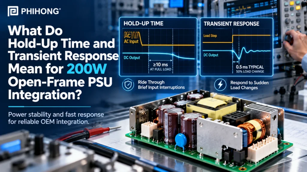
Hold-up time and transient response answer different integration questions. Hold-up concerns usable output during a defined input interruption. Transient response concerns output behavior when load changes. Neither figure alone establishes that an OEM device will remain operating through every power event.
The Phihong PBL200S family datasheet lists hold-up time of at least 10ms at full load and a typical 0.5ms transient response for a 50% load change. Preserve those qualifiers. The concise source does not fully specify the input test point, output threshold, step slew rate or recovery band, so the numbers are screening references that require further definition for system qualification.
Which timing values belong to which electrical event?
Start by separating the event that triggers the measurement. An input interruption, a load step and initial power application create different questions. The source also lists startup time below 3,000ms and rise time below 50ms. Those are separate entries, not alternative names for the hold-up or transient response figures.
Ask for the measurement boundaries before using any entry as an equipment requirement. For example, a rise-time value does not by itself establish the entire time from applying AC input to a functioning device. The document’s concise format leaves several timing definitions and test conditions unstated. Keep those gaps visible instead of combining the figures into an invented sequence.
| Metric | Source statement | Information still needed |
|---|---|---|
| Hold-up time | At least 10ms at full load | Input test point, interruption and output threshold |
| Transient response | 0.5ms typical for 50% load change | Step endpoints, slew rate, excursion and recovery criterion |
| Startup time | Below 3,000ms | Timing reference points and test conditions |
| Rise time | Below 50ms | Voltage thresholds and test conditions |
Record the exact voltage variant, load and cooling arrangement with the timing evidence. The family’s nominal 200W class does not erase the listed 150W convection and 200W fan-cooling distinction.
Why This Matters
- Using the wrong timing metric can approve a requirement that was never measured.
- Short specification entries need defined boundaries before becoming system acceptance criteria.
What OEMs Should Do Now
- Map each equipment power event to the relevant timing requirement.
- Request the supplier’s definitions and test conditions for the selected variant.
Useful Links
PBL200S output timing specifications
FEATURED PRODUCTS
PBL200S-120
- Output Power - 200W(with Fan)
- Output Volt - 12Vdc
- Features - Class B EMI , High Efficiency Performance , OVP, OCP, SCP, OTP Protections , Operating Altitude: 5,000M
PBL200S-240
- Output Power - 200W(with Fan)
- Output Volt - 24Vdc
- Features - Class B EMI , High Efficiency Performance , OVP, OCP, SCP, OTP Protections , Operating Altitude: 5,000M
PBL200S-480
- Output Power - 200W(with Fan)
- Output Volt - 48Vdc
- Features - Class B EMI , High Efficiency Performance , OVP, OCP, SCP, OTP Protections , Operating Altitude: 5,000M
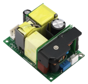
What does the full-load hold-up statement mean for the equipment?
Hold-up is relevant when input power is interrupted while the equipment still needs usable DC output. The supply’s stored energy and the load affect that behavior, while the equipment’s accepted voltage threshold determines when the output stops being useful for that function. Establish the actual event and measurement boundary rather than treating a timing label as a complete backup-power specification.
The PBL200S source states at least 10ms at full load, but does not identify the full input and output-threshold conditions alongside that entry. Do not generalize it into a promise for every line condition, repeated interruption or downstream rail. A converter, controller or other load may have its own undervoltage behavior that changes the equipment-level result.
| Item | Requirement to define |
|---|---|
| Input event | Specified interruption or disturbance and starting input condition |
| Load | Exact concurrent equipment demand and cooling configuration |
| Useful output window | Voltage threshold relevant to the load and intended function |
| Equipment outcome | Permitted behavior, shutdown or recovery requirement |
If the product needs controlled shutdown, retain the entire power path and sequencing requirement. The source’s hold-up entry does not prove that the device has enough time to complete that process, save data or preserve every function.
Why This Matters
- The equipment’s accepted output window can differ from an unspecified supplier test threshold.
- A brief hold-up reference is not a system backup or shutdown guarantee.
What OEMs Should Do Now
- Define the interruption case and minimum useful voltage for the actual loads.
- Test output and equipment behavior together under the agreed input and load conditions.
Useful Links
PBL200S-240 model record for a 24V candidate
How should the typical 0.5ms load-transient figure be evaluated?
A load change can disturb the output while the supply and connected power network respond. Evaluate the voltage excursion, subsequent behavior and equipment function, not just a single response-time number. The actual step endpoints, transition rate and measurement connection can affect the observed waveform.
The PBL200S entry says 0.5ms typical for a 50% load change. It does not establish that the step runs from zero to half load, from half to full load or another specified pair. It also does not state a guaranteed excursion or a voltage band defining recovery. Preserve “typical” and ask for the missing conditions before accepting a system requirement on that basis.
| Parameter | Reason to record it |
|---|---|
| Initial and final current | Defines what the stated step magnitude represents |
| Transition rate and duration | Describes the event applied to the output |
| Voltage measurement point | Separates supply behavior from distribution effects |
| Excursion and recovery criterion | Connects the waveform to the equipment’s accepted voltage window |
| Equipment functions | Shows whether the actual product requirement was met |
Use a test arrangement appropriate to the electrical system and retain both current and voltage evidence. TI’s load-transient application note is useful background on measurement methods; it does not establish the PBL200S rating or a pass result for your equipment.
Why This Matters
- A typical response reference cannot establish a guaranteed voltage excursion for an unspecified step.
- Measurement and distribution conditions can change the result observed at the load.
What OEMs Should Do Now
- Specify the real load events and acceptable output behavior before testing.
- Obtain the supplier step conditions and capture comparable current, voltage and functional evidence.
Useful Links
TI AN-1733 on load-transient testing
Why are regulation and ripple not substitutes for timing tests?
The family datasheet separately lists ±5% load regulation as typical and ripple/noise of no more than 1% Vp-p at full load. Those entries describe different characteristics from input-interruption tolerance and load-transient response. Do not use a typical static regulation entry as the guaranteed maximum excursion during an unspecified dynamic event.
Likewise, the full-load ripple statement does not settle every measurement condition or the device’s accepted rail behavior. Keep the applicable supplier test method and the load’s input requirement together. The integration record should distinguish static voltage behavior, periodic noise, dynamic events and usable output during input interruption.
| Characteristic | Evidence focus | Unjustified shortcut |
|---|---|---|
| Load regulation | Output behavior across defined steady loads | Assuming the same limit covers every transient |
| Ripple and noise | Waveform and method under specified load | Treating ripple as interruption tolerance |
| Transient response | Output behavior during the defined current step | Using typical timing as a reset guarantee |
| Hold-up | Usable output after the defined input event | Treating the entry as continuous backup power |
Translate the findings into the equipment’s acceptance criteria. A requirement such as “the controller completes the defined operation” needs functional evidence alongside the relevant rail measurements. No single source entry proves the whole behavior.
Why This Matters
- Combining separate specifications can create limits the manufacturer never stated.
- Equipment acceptance depends on the relevant electrical event and function.
What OEMs Should Do Now
- Keep regulation, ripple, transient and hold-up tests separate in the qualification matrix.
- Associate each result with its conditions, measurement point and functional acceptance.
Useful Links
PBL200S regulation, ripple and timing entries
How should OEMs close PBL200S timing questions with Phihong?
Name the required variant: PBL200S-120, PBL200S-240 or PBL200S-480. Provide the input-event definition, concurrent load, cooling arrangement, accepted voltage window and equipment behavior. Include representative load-step captures where available.
Ask Phihong to clarify the full-load hold-up input point and threshold, the transient test endpoints and slew rate, and the criterion behind the typical response entry. Obtain the current released document and relevant test information rather than assuming the concise summary is a complete validation procedure.
Keep source corrections and release status separate from measured system results. The document’s PBL2000S header spelling differs from the canonical product names, and its dimensions contain an inconsistency. Neither issue should change a model number in the purchasing record without supplier confirmation. Current availability and applicable approval evidence also need their own confirmation.
Why This Matters
- A defined event and voltage window give the supplier a concrete timing requirement to assess.
- Released model traceability prevents editorial or summary inconsistencies from becoming manufacturing inputs.
What OEMs Should Do Now
- Send the event definitions and missing test-condition questions to Phihong.
- Retain the clarified specifications and system qualification results with the selected configuration.
Useful Links
Review PBL200S timing and integration requirements
Related Links
Phihong’s broader open-frame power supply integration guide
Use the timing entries for the events they describe, preserve their qualifiers and qualify the actual supply-load path. Contact Phihong with the required interruption, load-step and equipment behavior to close the source gaps before release.
Frequently Asked Questions
Does the 10ms hold-up statement cover every input condition?
The source states at least 10ms at full load, but does not fully identify the input point or useful-output threshold with that entry. Do not assume universal coverage across line conditions and interruptions. Request the complete conditions and evaluate the actual equipment’s accepted voltage and function.
Does 0.5ms transient response guarantee that a controller will not reset?
No. The figure is typical for a 50% load change, with the detailed step and recovery criteria unstated. Controller behavior depends on the actual voltage waveform and its accepted input window. Test the relevant load event and controller function instead of treating the response-time reference as a reset guarantee.
Is a 50% load change necessarily a zero-to-half-load step?
The reviewed entry does not define the endpoints. A stated percentage change is incomplete without initial and final current, transition rate and duration. Request the supplier’s test conditions and specify the event relevant to your device so results can be compared meaningfully.
Are startup time and rise time the same specification?
They are listed separately: startup below 3,000ms and rise below 50ms. The concise source does not fully define their timing boundaries. Do not substitute the rise-time entry for the entire startup process or infer a complete equipment boot time from either value.
What makes a timing test useful for an OEM release?
Retain the exact supply variant, cooling configuration, input conditions, load event and measurement points. Define the accepted voltage window and equipment behavior before testing, then record the observed waveforms and functional result. Separate supplier specification references from your measured qualification evidence.