









BLOG
Multigigabit PoE: Why Does an Access Point Power Up but Negotiate Only 1GbE?
QUICK LINKS

A powered access point can report a 1GbE wired uplink even when the model supports 2.5GbE. PoE and Ethernet link negotiation are separate functions. The correct response is to isolate the link path while preserving the power source and the device state as much as possible.
Quick answer. Verify the actual switch port and access point support 2.5GbE, then test a known-good reference path, the injector and the full channel in sequence. Record negotiated rate and errors at both ends. A power indicator only establishes an observation about power.
Why This Topic Matters Now
Many multigigabit upgrades inherit switches with a mixture of port capabilities and cabling installed for earlier equipment. Two ports that look alike may advertise different supported rates, and a short patch cable does not represent the complete field channel. An injector can add power without changing what either Ethernet endpoint can negotiate.
Start by identifying the affected physical ports. Write down device model, hardware and firmware revision, relevant settings, injector identity and both patch cords. An observation attached to a switch name but not a port number is often impossible to reproduce.
For the wider decision, start with the complete injector qualification process. Then connect this result with packet errors under load. The earlier multigigabit poe guide provides the broader engineering background.
- Confirm powerPSE class, PD requirement and channel
- Verify the wired linkNegotiated rate and interface counters
- Test service recoveryTraffic, restart and application readiness
Conceptual qualification workflow. Each result belongs to the exact tested configuration.
Which components must support 2.5GbE?
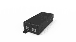
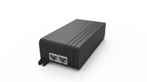
Check the precise switch port and access point interface, including configuration or restrictions that apply to the deployment. Confirm the injector model and hardware revision. The POE29U-1AT(PL)D-R page and model-specific datasheet list 2.5 Gigabit compatibility. If an older document or purchase record identifies a different speed, resolve the discrepancy with the supplier for the equipment in hand.
| Component | Evidence to check |
|---|---|
| Switch | Exact port capability, configuration and negotiated status |
| Access point | Wired uplink capability and device-reported rate |
| Midspan injector | Model, revision and supported path |
| Channel | Patch leads, termination points and field cable |
Avoid forcing speed as a first response. A change can conceal the original negotiation behavior or create a different test configuration. Record the supported settings, advertised capabilities and result before changing port policy.
How should OEMs isolate the cable channel?
Start with a reference link using known-good endpoints and appropriate short patch leads, powered through a supported means for the test. Establish the intended negotiated rate. Add the exact injector and patch connection, then check the full channel. Substitute one cord or segment at a time if the rate drops.
| Test step | What a change suggests |
|---|---|
| Reference endpoints and known-good path | Baseline endpoint or configuration behavior |
| Add injector with reference cords | Effect associated with the introduced device or connection |
| Insert the planned field path | Effect associated with field cabling or intermediate hardware |
| Substitute one segment | Narrows the cause to a repeatable change |
Use the organization’s approved cabling verification method when a segment is suspect. A path can negotiate a rate intermittently while still showing errors. Keep the negotiated rate and counter changes together rather than recording only the initial link state.
What can counters reveal after link comes up?
Collect error counters and link event history from both ends. Use deltas over a stated test period so older errors are not mistaken for new ones. Link flaps and physical errors during sustained traffic can reveal a marginal path that appears to negotiate correctly at idle. Record direction, duration and offered traffic while comparing configurations.
If the path stays at 1GbE with clean counters, review endpoint and port capability again before assuming the cable is at fault. If the rate moves between 1GbE and 2.5GbE, check whether the changes correlate with a specific segment, connector, device or operating condition. When only wireless throughput is poor, use a wired test to separate Ethernet behavior from radio variables.
When can the installation be released?
Define the required negotiated rate and acceptable observed link behavior before the test. Keep the exact topology, traffic results and approved hardware identifiers with the release record. If the deployment intentionally supports both 1GbE and 2.5GbE configurations, label which performance assumptions and service instructions belong to each.
A verified solution is one that repeats on the released configuration. If a test only passed with a temporary replacement cable, add that cable to the approved design or repeat the test with the intended field part. Keep the original failure evidence for future troubleshooting.
Key Takeaways
Verify the endpoints and exact injector, then add channel components one at a time. Use negotiated rate, error counters and wired traffic to isolate the behavior. Preserve the approved path and configuration for field teams.
Product and OEM Resources
FAQs
Can an access point receive power when it links at a lower speed?
Yes. A valid power state does not establish the negotiated Ethernet rate.
Should an injector be assumed to add multigigabit capability?
No. Confirm support across both endpoints and the complete data path.
Can I use a Wi-Fi speed test to validate the injector’s wired link?
Use port negotiation, interface counters and a wired test for that decision. A wireless test adds other variables.