









BLOG
PoE Injector Diagnostic LEDs: How Do You Separate Detection Failure from Overload or a Short?
QUICK LINKS

Quick answer. Use the LED table for the exact injector suffix and record both color and blink pattern. On the POE90U-1BT-X-R, an alternating amber/green short blink identifies a detection-failure indication, while a long/fast amber blink identifies an output overpower-or-short indication. Those are different investigation stages. The same family datasheet also contains a red-based table for other variants, so copying a generic PoE90 LED legend can mislead service teams. Treat the indication as a diagnostic clue, then correlate it with the camera, channel and event timeline.
This guide uses POE90U-1BT-X-R and its technical datasheet as the model reference. Apply the documented conditions to the actual equipment configuration.
Why This Topic Matters Now
A technician may report a blinking light without identifying its cadence or the model label beside it. That description can send the next person toward the wrong diagnosis, especially when related products use different colors for similar states. The first useful action is to capture the exact indication and configuration. A short video with the label and event context is often more informative than a still image of one moment in the blink cycle.
The PoE restart guide distinguishes receiver reboot, interface detection and upstream interruption. The LED review adds another observation to that timeline. It does not replace electrical or functional evidence and should not be presented as a guaranteed component-level diagnosis. A reported overload indication can point to several possible causes in the complete configuration, while a detection indication concerns an earlier stage of establishing the power interface.
| Service record | Include | Why |
|---|---|---|
| Product identity | Full injector suffix | Selects the correct LED table |
| Color | Observed indicator colors | Distinguishes variant-specific behavior |
| Cadence | Short/slow, long/fast or alternating | Preserves the documented meaning |
| Event context | Before, during and after connection | Identifies the stage of failure |
Why This Matters
- A blink description without model and cadence is incomplete evidence.
- An indication narrows the investigation but does not establish a root cause.
What OEMs Should Do Now
- Record the full label and a short indication sequence.
- Keep the correct model-specific table with service documentation.
- 1. Confirm source and PD
- 2. Exercise camera modes
- 3. Check cable and location
- 4. Verify service recovery
Conceptual workflow, not a test result or certification statement.
Read the X-R Indications Without Borrowing the Red-Based Table
The applicable datasheet groups the X-R with the 2-R and 5-R variants for its amber/green diagnostic table. It separately lists a red-based table for other family models. Use the matching section and document revision rather than a remembered color legend. Record an indication exactly enough that another technician can compare it with the source document, including whether more than one color alternates.
For the X-R table, blue indicates power on, a short/slow amber pattern indicates readiness without a connection and solid green indicates good PoE output power. An alternating short amber/green pattern indicates detection failure, a long/fast amber pattern indicates output overpower or short and blinking green indicates an invalid-load condition. No LED is listed as power failure. These indications describe the source’s reported state rather than proving the camera’s full operation.
| X-R indication | Datasheet meaning | Investigation boundary |
|---|---|---|
| Blue on | Power on | Not a complete camera test |
| Amber short/slow blink | Ready without connection | Expected connection not established |
| Green steady | PoE output power good | Data and camera still need verification |
| Amber/green alternating short blink | Detection failure | Review the supported interface and path |
| Amber long/fast blink | Output overpower or short | Review the output condition |
| Green blinking | Invalid load condition | Review receiver and interface evidence |
Why This Matters
- The wrong family table can change the interpretation of the same reported color.
- Power-good status does not prove video, control or every camera mode.
What OEMs Should Do Now
- Attach the X-R table and document revision to the service record.
- Verify camera functionality separately from the source indication.
Investigate Detection Before Treating It as a Running-Load Failure
A detection-failure indication belongs to the process of establishing a suitable power connection. Check the exact receiver interface, approved cable and connection path using the equipment’s service procedure. Confirm that the intended device is actually connected to the correct ports. A known-good supported reference configuration can help isolate whether the symptom follows the receiver, channel or source, provided each substitution is controlled and documented.
Do not attempt to solve an unexplained detection problem by bypassing detection, improvising wiring or assuming the proprietary detection feature supports every legacy load. Request explicit evidence for nonstandard pairings. The PoE qualification guide supplies the complete source-channel-device method, and the power-budget article becomes relevant after the required interface and allocation have been established. Keep those stages distinct in the report.
| Detection-stage check | Evidence | Useful interpretation |
|---|---|---|
| Receiver identity | Exact model and supported interface | Confirms the intended pairing |
| Connection path | Approved channel and port arrangement | Identifies configuration errors |
| Reference comparison | Known-good supported combination | Localizes the symptom |
| Proprietary dependency | Explicit supplier support | Prevents an unsupported compatibility claim |
Why This Matters
- A device that never establishes the interface needs a different investigation from one failing under load.
- Bypassing interface behavior removes the evidence needed for a compatibility decision.
What OEMs Should Do Now
- Confirm the supported pairing and released path before load testing.
- Document one controlled substitution at a time.
Correlate an Output Indication with the Load and Event Timeline
When the indication concerns output overpower or short, retain the sequence of camera states that preceded it. Did the camera begin a permitted heater mode, change infrared lighting or move a motor? Record suitable source and receiving measurements alongside the indication where the approved test arrangement allows. Do not intentionally short a live installation or create an uncontrolled fault merely to reproduce a color pattern. Use qualified equipment procedures for any protection investigation.
The indication does not tell a service team whether the cause is excessive demand, a damaged path or another output condition. Inspect and compare the released configuration through the approved troubleshooting process. The packet-error guide adds the data observations needed when the camera remains powered but network performance changes. Preserve the event record before power cycling because a reset can erase the sequence that distinguishes the possibilities.
| Event evidence | Record | Purpose |
|---|---|---|
| Camera mode | Supported function and firmware | Identifies the preceding demand change |
| Electrical behavior | Appropriate source and receiving traces | Shows the output condition |
| Channel condition | Cable and connection identity | Supports a controlled comparison |
| Functional behavior | Video, control and restart timeline | Establishes the consequence |
Why This Matters
- The same indication can have more than one underlying cause.
- A power cycle may remove information needed to understand the failure sequence.
What OEMs Should Do Now
- Capture the indication and operating state before an approved restart.
- Use qualified procedures and suitable instrumentation for protection-related testing.
Close the Service Case with a Reproducible Result
A complete service note should state the original indication, confirmed configuration, investigation steps and final result. If replacing a cable resolves the symptom, repeat the original trigger under the released operating conditions rather than stopping at a single successful boot. If the root cause remains uncertain, say which evidence is missing and assign the next review. Avoid declaring an injector defective solely because it reported a fault state.
Keep the approved LED reference and replacement rules with the equipment configuration. A different source suffix can require a different service legend or data-capability review even when nominal wattage matches. The PoE system pillar supports broader architecture decisions, while the Phihong PoE product discussion guide helps frame unresolved questions for supplier review. A useful outcome is a diagnosis another technician can reproduce and a configuration the team can support.
| Case-close item | Record | Decision supported |
|---|---|---|
| Original symptom | Exact color, cadence and timing | Preserves the failure evidence |
| Controlled changes | One item and result at a time | Supports the diagnosis |
| Repeat test | Original operating trigger | Confirms the remedy |
| Approved configuration | Model, channel and service legend | Prevents an unsupported substitution |
Why This Matters
- A repeatable result is stronger evidence than one successful restart.
- Service references must stay aligned with the exact released product variant.
What OEMs Should Do Now
- Retest the original trigger after a proposed remedy.
- Update the service record with supported replacements and any unresolved question.
Key Takeaways
Match the LED table to the full injector suffix, then record color, cadence and event timing. Keep detection-stage and output-stage investigations separate. Correlate indications with the camera and channel, preserve evidence before restarting and confirm a remedy by repeating the original trigger under controlled conditions.
Featured Products
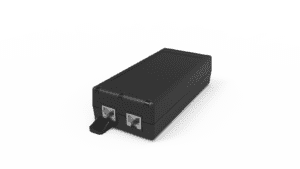
Explore the reference product and focused alternatives using Phihong manufacturer photographs. Each model requires its own configuration and documentation review.

POE90U-1BT-X-R
10G reference model. 90W source rating and documented four-pair behavior.
Manufacturer photograph; some variants share a family image.
POE90U-1BT-2-R
2.5G alternative. Select the supported data rate and verify current model availability.
Manufacturer photograph; some variants share a family image.
POE90U-1BT-5-R
5G alternative. Review its own model configuration rather than assuming interchangeability.
Manufacturer photograph; some variants share a family image.
Technical References
Use the applicable complete documents and current model evidence for the equipment review.
Related Product Options
The models below support a focused comparison. Regional variants and different power classes need their own documentation and final equipment review. This comparison does not establish drop-in interchangeability.
| Model | Reason to consider | What to verify |
|---|---|---|
| POE90U-1BT-X-R | 10G reference model | 90W source rating and documented four-pair behavior |
| POE90U-1BT-2-R | 2.5G alternative | Select the supported data rate and verify current model availability |
| POE90U-1BT-5-R | 5G alternative | Review its own model configuration rather than assuming interchangeability |
Product and OEM Resources
FAQs
What does alternating amber and green mean on the X-R?
The matching datasheet table identifies an alternating short amber/green pattern as a detection-failure indication. Confirm the exact cadence and model before interpreting it.
What does a long, fast amber blink indicate?
For the X-R table it indicates an output overpower-or-short condition. The indication does not identify the failed component; investigate the complete configuration using approved procedures.
Can I use a red-LED legend from another POE90 model?
Use the table matching the exact suffix. The family datasheet contains separate red-based and amber-based tables, so a generic legend can mislead troubleshooting.
Does solid green prove the camera works correctly?
It indicates good PoE output power in the matching table. Verify camera functions, data performance and supported operating modes separately.
Should a technician create a short to check the indication?
Do not create an uncontrolled fault in a live installation. Any protection investigation should use suitable equipment and qualified, approved test procedures.