










BLOG
3×7-Inch Open-Frame PSUs: Will the Replacement Fit Once You Account for Standoffs and Wiring?
QUICK LINKS

A replacement open-frame supply can fit inside the outline on a cabinet drawing yet collide with a wire duct after its harness is connected. The difference is the installed envelope. It includes board and component height, mounting hardware, mated connectors, cable exit, insulation and the space required to work on the assembly.
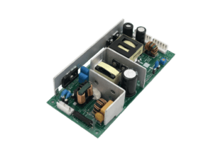
Quick answer. Check a shared cabinet datum against the exact drawing, build up the standoff and harness dimensions and inspect the closed production enclosure. Phihong lists the BI150-240A-R at 160 × 75 × 37 mm in its model-specific drawing and datasheet. Use that exact envelope and hole pattern when evaluating a part described by a nominal frame size.
Why This Topic Matters Now
A retrofit frequently inherits a fixed enclosure and a fixed service routine. Those constraints matter more than the shorthand used in a catalog. A mounting plate can solve hole alignment but add enough height to move a connector into a cover or force wiring into a heat path. Parts that look interchangeable in a purchasing list can therefore have different assembly costs and different compliance implications.
Ask the mechanical designer for an installed stack-up and the service lead for the expected swap sequence. Review both before locking the BOM. If a technician must disconnect an unrelated branch to remove the supply, record that dependency in the service procedure or change the layout.
For the wider decision, start with the complete retrofit qualification process. Then connect this result with cabinet temperature measurement. The earlier industrial retrofit guide provides the broader engineering background.
- Define the machineLoad, cabinet and installation requirements
- Evaluate the retrofitFit, startup, temperature and EMC
- Release the configurationApproved supply, harness and service record
Conceptual qualification workflow. Each result belongs to the exact tested configuration.
What dimensions belong in the mounting stack-up?
Choose one datum and dimension the enclosure, adapter plate and board from it. Include the fastening hardware and supports, the underside of the board, the tallest component and the inside surface of the cover. Build in the documented tolerance of the parts and check the relationship with barriers or other circuits. Ask the responsible compliance engineer to confirm required electrical distances using the product and end-equipment requirements.
| Stack-up item | What to check |
|---|---|
| Plate and supports | Hole pattern, mounting height and hardware interference |
| Board underside | Clearance to hardware, metal surfaces and neighboring conductors |
| Tallest points | Exact locations relative to door, sidewalls and insulation |
| Normal service access | Room to operate intended connectors and remove fasteners |
Two boards can share a nominal width but put their tallest parts in different places. Rather than check height at the center only, overlay the drawing against the lid, nearby components and any mounting rails. Record the first point that loses margin in the worst allowed assembly tolerance. This becomes a practical inspection point when production changes a plate supplier or enclosure revision.
Where does the harness change the fit calculation?
Place the mating connector and the actual wire bundle into the model. Account for the connector body, retention features, labels, sleeving and the transition from the connector to the first tie-down. A thicker option harness may require different routing or may load the connector sideways when the door closes.
| Harness feature | Review question |
|---|---|
| Wire exit | Does the mated connector face a wall or adjacent module? |
| First restraint | Can the wire follow the approved path without tension? |
| Service loop | Is there enough slack for removal and enough control in normal use? |
| Alternate harness | Does the highest option count change bundle size or routing? |
Use a mated sample to check technician access and retention. Mark the reference points for tie-downs or wire ducts and add photos to the assembly record. A strain relief that works with a bare harness on a bench may be inaccessible once adjacent equipment and guards are installed.
What should a physical mockup establish?
Build with the production plate, approved supports and wiring, barriers, neighboring modules and cover. Have an assembler install the replacement in the normal order. Note where the process relies on temporary moves that would be difficult to repeat in the field. Close the enclosure and verify its final condition through the approved inspection method.
Exercise the removal path as well. If the replacement can be removed only after pulling the harness across another assembly, the service process has a new failure mode. Ask quality and service to agree whether a fixture, alternate sequence or physical change is the right control.
| Trial | What a useful record contains |
|---|---|
| First assembly | Part revisions, orientation, mated photos and any forced rework |
| Closed cabinet | Clearance inspection and approved harness positions |
| Service simulation | Tool access, removal order and final reassembly checks |
Keep the approved photos at the same orientation as the work instruction. Use closeups for the locations that are difficult to describe. A photo should show what good looks like, with a separate controlled drawing where dimensions matter.
How should OEMs account for cooling and compliance during fit review?
A board that fits can still sit in a blocked convection path. Look at where cooler air enters the local region and where warmed air can escape. An adapter plate can alter both paths. Compare the mockup with the orientation and installation conditions for the model, then use installed thermal tests to establish whether the selected arrangement supports the intended duty.
Check whether the change also moves input and output wires or modifies a bond to the chassis. Those changes can affect EMC and the final electrical safety configuration. Record the decision in the release package so the next retrofit team can distinguish approved layouts from ones that merely fit.
Key Takeaways
Treat standoffs, the mated harness and service access as part of the supply envelope. Compare the exact product drawing with a closed, production-representative assembly. Document the approved path and its thermal and compliance implications before approving a repeatable retrofit.
Product and OEM Resources
FAQs
Is 3×7 a mounting standard?
Treat it as a nominal form-factor description. Use the exact drawing for mounting, dimensions, connector positions and tolerances.
Can we reuse the old standoffs if the holes line up?
Check height, board underside clearance, the approved fastener stack and the applicable bonding and safety requirements before reuse.
When should the harness be installed in the mockup?
Install the production harness before closing the cabinet and check representative options, mated connectors, restraints and service access.