









BLOG
Rack PSU Fault Recovery: Why Does 12V Stay Off While Standby Power Recovers?
QUICK LINKS

Quick answer: 12V can stay off while standby recovers because the PA350R source lists latching recovery for several main-rail faults and auto-recovery for several standby faults. The rails need not return together. Confirm the event and controls before deciding which behavior occurred.
The PA350R-212A-R 350W rack supply is a useful model-specific example, not a universal rule for all rack PSUs. A restored management interface proves only that the path powering it is available at that moment. It does not prove the main fault is cleared or the main output is enabled.
Begin by preserving evidence and identifying the initiating condition. Recovery is a controlled system operation, not simply a command that makes a warning disappear. This article separates rail recovery, fault-status clearing, re-enabling power and successful validation.
Read the protection behavior for each rail separately
The PA350R technical source describes latching behavior for main-output overcurrent, overvoltage, undervoltage and short circuit. Its standby overcurrent, overvoltage and short-circuit entries specify auto-recovery. Overtemperature is also listed as auto-recovery. Preserve the exact rail and protection entry instead of summarizing the whole unit as either “latching” or “self-recovering.”
These differences make an asymmetric endpoint plausible: standby returns while 12V remains unavailable. They do not establish which fault initiated the event. A commanded main-off state can look similar after the fact, and an unresolved condition may cause repeated attempts. The protection table needs to be combined with the actual control history, status and rail observations.
Avoid transferring a recovery procedure from another adapter or PSU family. Even when protection names are the same, reset conditions and system interlocks can differ. Use the current project revision and approved system method. The source’s behavior labels are a diagnostic reference, not a complete set of service instructions or permission to force a restart.
| Source protection entry | Main 12V | Standby |
|---|---|---|
| Overcurrent | Latch | Auto-recovery |
| Overvoltage | Latch | Auto-recovery |
| Short circuit | Latch | Auto-recovery |
| Undervoltage | Latch | No standby behavior inferred here |
Why This Matters
- Recovery behavior belongs to a specific rail and protection condition.
- The final rail state alone cannot identify the initiating fault or reset requirement.
What OEMs Should Do Now
- Match the observed event to the exact model, revision, rail and protection entry.
- Keep normal control shutdown separate from unexpected fault recovery.
FEATURED PRODUCTS

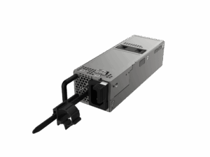
PA350R-212A-R
- Output Power - 350W
- Output Volt - 12V
- Features - This rack-mount power supply accepts AC line input voltage from 100Vac to 240Vac or DC voltage from 180Vdc to 300Vdc,provides 350 watts of 12Vdc main and 5Vdc standby power. This high power density power supply features a fully digital design, supports the PMBus communication protocol, and is equipped with short circuit, overcurrent, over-voltage, and over-temperature protection.
Preserve the initiating evidence before clearing status
Save the supported fault record, control state and rail observations before any clear or reset action. Include AC_OK and PW_OK, module identity, available status groups and the preceding load or environmental event. Distinguish the first reported abnormal condition from the conditions recorded after the output was already off. A later undervoltage observation may describe the endpoint rather than its cause.
A management interface that returns after standby recovery can help retrieve evidence, but some records may have different retention behavior. Do not assume a rebooted controller preserved everything. Note gaps and the time at which information became available again. Preserve the raw data and the decoded interpretation so a later review can check whether software assigned the right meaning.
Avoid repeated recovery cycles as a first diagnostic technique. They can erase sequence information, create additional events and leave the initiating issue unresolved. A carefully documented initial event is often more useful than several resets that produce an inconsistent mixture of old and new status. Follow the approved incident and service procedure while evidence is collected.
Why This Matters
- Clearing or cycling early can remove the information needed to explain why the latch occurred.
- A recovered controller may report a later state with incomplete event history.
What OEMs Should Do Now
- Export available read-only status and time-aligned controls before any approved recovery.
- Mark evidence gaps and distinguish initiating events from consequences of output loss.
Distinguish clearing a report from re-enabling the main rail
The command table includes CLEAR_FAULTS. The PS_ON description separately states that a high-to-low transition turns on 12V and clears fault. Do not infer from these entries that a CLEAR_FAULTS command alone releases every latched main fault in every configuration. The applicable recovery sequence, prerequisites and interlocks require revision-specific confirmation.
A successful management transaction proves the target accepted or responded to that transaction according to its interface behavior. It does not by itself prove that 12V returned, that PW_OK asserted or that the original cause was corrected. Observe those outcomes separately through the supported system interface. Keep the requested action and the measured result as different entries in the record.
Do not invent a power-cycle duration or manually force control pins to implement a reset. Use the approved platform recovery method, which must account for other installed modules, load state and service conditions. If the correct procedure is not defined, obtain it from Phihong and the platform team before automation depends on a guessed sequence.
| Outcome | Evidence needed |
|---|---|
| Status cleared | Supported status readback |
| Main rail available | Approved rail observation and relevant validity state |
| Cause resolved | Confirmed corrective action and appropriate validation |
| Device recovered | Successful application sequence under its requirements |
Why This Matters
- Status clearing, latch release and output availability are different outcomes.
- An acknowledged command can coexist with an unavailable main rail or unresolved condition.
What OEMs Should Do Now
- Confirm the exact approved reset prerequisites and sequence for the delivered revision.
- Verify main voltage, output-valid state and application behavior after the authorized operation.
Remove the cause before treating recovery as success
A rail that returns briefly can still be responding to an unresolved load, thermal or system condition. Recovery should therefore include an explanation of what changed and evidence that the initiating condition has been addressed. Do not describe repeated automatic restart as proof of healthy operation. Preserve any recurrence and stop the experiment according to the approved procedure rather than repeatedly forcing power.
The redundant PSU guide explains why other modules may maintain a shared bus while one unit is unavailable. That can complicate verification: normal bus voltage does not prove the recovered module contributes as intended. Associate rail and management observations with the same physical unit, and assess the installed redundancy state against the qualified platform design.
Validate at an agreed operating condition after recovery, then check the relevant application sequence. A management warning disappearing is not equivalent to successful device operation. The appropriate validation depends on the event and program; do not invent a universal stress test or overload sequence. Document the result and any remaining limitation so the issue is not closed solely because the system can be powered again.
Why This Matters
- Temporary rail return and correction of the initiating problem are different achievements.
- A healthy shared bus can mask the state of an individual redundant module.
What OEMs Should Do Now
- Record the corrective action or resolved condition before evaluating recovery.
- Verify module-specific behavior and the application result under the approved validation plan.
How Phihong supports a rail-specific recovery procedure
For PA350R-212A-R, provide the exact revision, physical module/bay, initial fault sequence, control state, supported status and both rail observations. Ask which protection entry applies and what the approved recovery prerequisites are. Include whether standby remained continuous or disappeared and returned. That distinction helps separate normal shutdown, standby recovery and a retained main latch.
Confirm optional features and system implementation rather than relying on a generic recovery recipe. The public document identifies default standby behavior and optional capabilities, but the delivered configuration and platform interlocks control the actual method. A publicly listed command is not an authorization to issue arbitrary management writes to operating equipment.
Keep the confirmed procedure with the rack power-system documentation and use the main/standby architecture guide as context. A useful procedure states what evidence to preserve, what condition must be corrected, who can authorize the recovery operation and how success will be verified. It should leave no ambiguity between clearing a message and restoring qualified operation.
Why This Matters
- A revision-specific procedure avoids unsupported assumptions about latch release.
- Explicit success criteria prevent premature closure after a warning or rail briefly returns.
What OEMs Should Do Now
- Obtain the approved recovery method and preserve it with the configuration record.
- Close the issue only after the cause, module response and application validation are documented.
Useful Links: PA350R-212A-R product details · PA350R-212A-R technical datasheet
Related Links: Rack PSU diagnostic workflow · Main-off and standby states · PMBus address conflicts · Main and standby architecture · PMBus status context · Redundant module behavior · Rack power-system guide
Frequently Asked Questions
Can standby auto-recover while the main rail remains latched off?
The PA350R source lists different behavior for several main and standby protections, so that endpoint is plausible. Use the actual event and control record to establish what occurred.
Does CLEAR_FAULTS guarantee that 12V restarts?
Do not infer that from the command listing. Confirm the revision-specific recovery sequence and verify output behavior separately from status clearing.
Is a restored management interface proof the PSU is fully recovered?
No. It shows that its powering path is available at that moment. Main enable, main output, validity signals and the original cause still need verification.
Should I keep cycling the system until the latch releases?
Follow the approved service and recovery procedure. Repeated cycling can remove evidence and leave the initiating condition unresolved; preserve the initial record first.
What demonstrates a completed recovery?
A documented cause or corrective action, an approved recovery sequence, module-specific output/status verification and successful application validation under the relevant requirements.