









BLOG
Rack PSU Fault Signals: Why Do AC_OK and PW_OK Tell Different Stories?
QUICK LINKS

Quick answer: AC_OK and PW_OK can differ because they report different conditions: the PA350R source defines AC_OK high as valid AC/DC input and PW_OK high as a valid output rail. Input validity does not automatically mean the main rail is enabled or ready.
For the PA350R-212A-R rack PSU, interpreting the pair requires control state, event timing and rail evidence. The combination AC_OK high with PW_OK low can be consistent with several situations. It does not, by itself, identify a defective module or a particular protection event.
Use the signals to organize the next diagnostic question. Preserve the sequence, establish the physical module and compare supported status information before changing controls. This article focuses on discrete-signal interpretation rather than replacing the broader rack architecture or PMBus guides.
Treat input-valid and output-valid as separate observations
The PA350R datasheet defines the two signals separately. AC_OK concerns input validity, including the model’s supported AC/DC context. PW_OK concerns output validity. Keep those exact meanings in firmware labels and diagnostic screens. A generic green “power good” indicator that merges both can hide the distinction needed during a no-output investigation.
A connected source is not the same evidence as an asserted input-valid signal. Likewise, a measured voltage at one output point is not automatically identical to the PSU’s internal validity decision. Record the physical or supported logical observation and its time. If telemetry or a system abstraction is being used instead of the discrete signal, say so; the abstraction may include its own update interval or logic.
Do not interpret AC_OK as “all power rails good” or PW_OK as “every downstream device operating.” These signals have bounded roles. The complete system can have connector, distribution or receiver behavior beyond the module’s reporting boundary. Use the pair to narrow the investigation while retaining measurements at the relevant approved points.
| Signal high | Model meaning | Unsupported conclusion |
|---|---|---|
| AC_OK | AC/DC input valid | Main output must be on |
| PW_OK | Output rail valid | Every downstream load is healthy |
Why This Matters
- Clear signal labels preserve the difference between input availability and output readiness.
- A module status boundary does not cover every downstream system condition.
What OEMs Should Do Now
- Use separate input-valid and output-valid fields in engineering logs.
- Identify whether each recorded value is a discrete observation, telemetry value or system-derived state.
FEATURED PRODUCTS

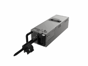
PA350R-212A-R
- Output Power - 350W
- Output Volt - 12V
- Features - This rack-mount power supply accepts AC line input voltage from 100Vac to 240Vac or DC voltage from 180Vdc to 300Vdc,provides 350 watts of 12Vdc main and 5Vdc standby power. This high power density power supply features a fully digital design, supports the PMBus communication protocol, and is equipped with short circuit, overcurrent, over-voltage, and over-temperature protection.
Interpret AC_OK high and PW_OK low without guessing the cause
This combination says the input is considered valid while output-valid is not asserted. It leaves several questions open: is main power commanded off, is startup still in progress, is an interlock active, or is a fault retaining the main rail off? Examine the supported main-enable and standby-control observations before choosing between them.
On PA350R, PS_ON low-to-high turns off 12V, while high-to-low turns it on and clears fault according to the source description. PS_KILL has a separate role involving standby and both outputs. A deliberately disabled main rail can therefore produce input-valid without output-valid. An unexpected event with the same final pair needs its command and fault history to be interpreted.
Avoid treating the combination as a replacement instruction. A component swap may conceal a platform control issue or erase the evidence of an earlier fault. Preserve the module identity, current rail observations and preceding sequence. The most useful next question is which expected condition for main-output availability has not been met, not which hardware to blame first.
| Evidence to add | Question it resolves |
|---|---|
| Main-enable state | Was 12V requested? |
| Standby observation | Is management power available? |
| Event timing | Is this a transition or persistent condition? |
| Fault record | Was an abnormal condition recorded before output loss? |
Why This Matters
- One signal pair can be consistent with normal control and several abnormal states.
- A premature hardware conclusion can leave the actual control or load issue unresolved.
What OEMs Should Do Now
- Check main-enable and interlock state through the supported platform interface.
- Correlate the signal pair with actual rail observations and the preceding command/fault history.
Use signal timing to distinguish transitions from persistent faults
Signal changes occur in a sequence. The PA350R timing table separately describes input-related, standby-related, main-output and PW_OK events. A snapshot during startup can legitimately show a state that would be suspicious if it persisted after the expected sequence. Identify the event interval before judging the combination.
The source includes a separate interval between 12V appearing and PW_OK assertion. Do not assume those events are simultaneous or infer a delay from a slowly updating management screen. Use the current agreed timing definitions and a capture method that can resolve the event. Preserve the time reference and measurement boundaries for every channel used in the comparison.
During shutdown or input loss, the ordering matters again. A fault log written after the electrical event may not identify the first change. Compare a known normal transition with the unexpected one, and note whether the earliest difference is input validity, enable state, output voltage or output-valid indication. That sequence is more diagnostic than a final two-bit state alone.
Why This Matters
- A temporary state and a persistent state can share the same final signal values.
- Logging latency can distort the apparent order of physical events.
What OEMs Should Do Now
- Capture the relevant transition with explicit markers and a known time base.
- Find the first deviation from a validated normal sequence before assigning a cause.
Correlate discrete signals with PMBus and measured rails
PMBus status can add detail to the signal pair, but it does not remove the need to identify the correct module and target. Use supported read-only status groups and rail telemetry as context. Preserve raw values as well as the controller’s decoded messages, and record communication errors rather than silently retaining an old “good” value.
A discrepancy between a measured rail and reported status can come from different boundaries, timestamps, validity thresholds, decoding or a genuine problem. Compare those possibilities systematically. Do not declare a signal stuck solely because a polled value disagrees with a brief analog observation. Equally, do not dismiss a persistent contradiction once the identity, method and timing have been checked.
The PMBus overview explains management functions, while the main and standby guide explains the separate rails. Use those as supporting context. For this diagnostic event, the value comes from aligning controls, signals, voltage/current observations and status around one module and one timeline. Save the evidence before clearing anything.
Why This Matters
- Different data sources become useful when their identity, boundary and timing are aligned.
- Stale or misdecoded telemetry can imitate a contradictory hardware state.
What OEMs Should Do Now
- Preserve supported status and communication results alongside signal and rail evidence.
- Resolve identity, decoding and timing differences before classifying a persistent contradiction.
How Phihong supports signal-state diagnosis
For a PA350R-212A-R review, provide the exact module revision, bay identity, AC_OK/PW_OK sequence, supported control states, standby/main observations and fault record. Explain whether the event followed startup, an intentional shutdown, input loss or an unexpected load condition. Ask about the first unexplained transition rather than sending only a final state screenshot.
Use approved interface documentation for electrical implementation. The source’s high/low interpretation thresholds do not define a complete drive circuit, connector rating or pull-up requirement. Do not force a signal to make a diagnostic screen change. Confirm the intended implementation and current specification with Phihong and the platform team when the observed behavior remains unexplained.
Keep the accepted signal definitions and representative normal sequence with the rack PSU architecture documentation. A useful production diagnostic rule should state what the pair establishes, what other evidence it needs and when it should escalate for review. It should not convert a non-unique signal combination into an automatic declaration that the module is defective.
Why This Matters
- A transition-based question helps separate a component issue from platform logic.
- Bounded diagnostic rules reduce false failures and unnecessary replacement decisions.
What OEMs Should Do Now
- Request review of the complete sequence and the applicable revision-specific definitions.
- Document the evidence required before any automatic recovery or replacement action.
Useful Links: PA350R-212A-R product details · PA350R-212A-R technical datasheet
Related Links: Rack PSU diagnostic workflow · Main and standby fault recovery · Main-off and standby states · Main versus standby operation · PMBus diagnostic context · Intelligent rack PSU guide
Frequently Asked Questions
Can AC_OK be high while PW_OK is low?
Yes. Input validity and output validity are different conditions. Check enable state, sequencing, interlocks and fault history before interpreting that combination.
Does AC_OK only refer to AC input?
The PA350R description defines the high state as AC/DC input valid. Use the exact model definition rather than inferring the scope from the signal name alone.
Does PW_OK prove every device has good power?
No. Its defined reporting boundary does not establish every downstream connector, distribution path or receiver condition. Validate the relevant system boundary separately.
Can a management screen miss the ordering of the signals?
Yes. Polling and log-update intervals may be slower than electrical transitions. Label the capture method and use time-aligned evidence when event order matters.
What should I do before clearing faults?
Preserve module-specific signals, controls, rail observations and supported fault/status information. Confirm the approved recovery sequence after the initiating condition has been investigated.