









BLOG
200% Power Boost: How Should OEMs Validate a 10-Second Peak Load on a 240W Supply?
QUICK LINKS
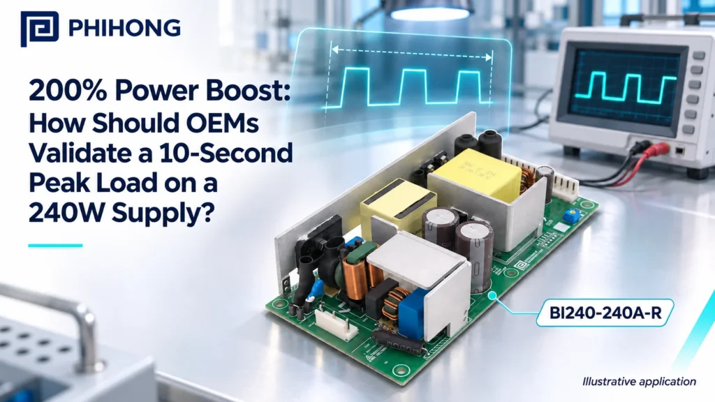
Quick answer. A short boost rating can help an OEM avoid sizing an entire power system around a load that occurs only briefly. It can also be misused when a test captures only the peak amplitude and misses duration, repetition or installed conditions. For Phihong’s BI240-240A-R, qualification should address the documented 20A peak and 480W boost boundary at nominal 24V, the maximum 10-second duration and the restriction on average power during repetitive operation.
This guide uses BI240-240A-R and its technical datasheet as the model reference. Apply the documented conditions to the actual equipment configuration.
Why This Topic Matters Now
A machine update can change the time spent in a high-demand state even when its highest measured current remains unchanged. A new acceleration profile, more frequent valve operation or a revised startup sequence may keep a supply in its demanding region longer. The useful comparison is the complete load-time waveform, not two isolated current maxima. Ask what actually changed between the released machine and the proposed configuration.
The broader industrial retrofit qualification guide covers mechanical, electrical and compliance evidence. This article isolates the boost test: define the event, reproduce its duty, observe the correct boundaries and decide what the evidence covers. Keep an isolated pulse demonstration separate from an approval for a repeating production cycle. That separation helps purchasing and the equipment team understand why two machines with the same peak current may need different power solutions.
| Change | Why a peak-only comparison misses it | Evidence |
|---|---|---|
| Longer acceleration | More time at high output | Event duration trace |
| Faster cycle | Less time between peaks | Full repeat period |
| Added concurrent load | Higher demand around the peak | Combined output waveform |
| Hotter installation | Different continuous allowance | Thermal and mounting record |
Why This Matters
- The peak number can stay constant while the relevant duty changes.
- Qualification should cover the cycle that will ship, including released firmware.
What OEMs Should Do Now
- Identify the physical event and its commanded sequence.
- Capture an entire cycle before choosing the boost test settings.
- 1. Define continuous demand
- 2. Capture peak and repetition
- 3. Apply installation limits
- 4. Verify equipment recovery
Conceptual workflow, not a test result or certification statement.
Turn the datasheet limits into separate test questions
The BI240 documentation distinguishes 10A continuous operation at 24V, 20A peak for up to 10 seconds and repetitive boost operation whose average power does not exceed the continuous 240W rating. Write a separate acceptance question for each condition. Do not report only that the supply reached 20A. That result does not describe how long it remained there, how voltage behaved or how often the event repeated.
An illustrative arithmetic example shows why duty matters. A cycle with 480W for two seconds and 120W for eight seconds averages 192W over ten seconds. That calculation is only a screening result; it does not establish that this pulse is an approved operating condition. The actual load shape, input, installation and documented limits still need review. Avoid converting a simple average calculation into a supplier endorsement of an unspecified machine.
| Question | Observation | Decision supported |
|---|---|---|
| How high? | Current and power amplitude | Comparison with specified peak envelope |
| How long? | Time in demanding state | Comparison with maximum duration |
| How often? | Complete repetition interval | Average-power screening |
| What happens afterward? | Voltage and machine readiness | Recovery and repeatability |
Why This Matters
- Average power is necessary for repetition review but does not replace all other limits.
- A calculation and a measured equipment result are different kinds of evidence.
What OEMs Should Do Now
- Label every worked calculation as illustrative or derived.
- Retain amplitude, duration, interval and recovery in the same test record.
Capture source response and receiving-circuit behavior together
Instrument the supply output and the receiving circuit that determines whether the machine completes its event. Keep measurement timing aligned so a voltage disturbance can be compared with the current transition. If a remote controller resets while the source terminals remain acceptable, examine the distribution path and shared connections. The startup voltage-dip investigation explains that distinction in the retrofit context.
Set a capture window that shows the pre-event state, the whole high-demand interval and enough recovery to establish the next cycle’s initial conditions. Record instrument settings and whether a trigger can miss an earlier excursion. Use the intended harness and load controls rather than assuming an electronic-load pulse reproduces a motor or a bank of downstream converters. A simplified load can characterize the source, while the final machine test establishes equipment behavior.
| Capture | Keep with the trace | Reason |
|---|---|---|
| Supply current | Probe location and range | Defines combined demand |
| Supply voltage | Terminal measurement point | Describes source response |
| Sensitive load input | Harness and connection identity | Shows delivered voltage |
| Controller event | Trigger or synchronized log | Connects electrical event to function |
Why This Matters
- A source trace cannot by itself establish voltage at every downstream circuit.
- A laboratory load and the installed machine may have different dynamic behavior.
What OEMs Should Do Now
- Document the measurement boundary before interpreting a dip.
- Use the machine’s functional acceptance criterion alongside electrical limits.
Repeat the event under the installation conditions that matter
Apply the relevant input, temperature and mounting conditions rather than repeatedly testing one comfortable bench configuration. The BI240 datasheet includes derating requirements, so the continuous allowance used in the duty review must come from the applicable installation conditions. Keep air temperature and orientation observations tied to the exact mounting arrangement. A supply placed openly on a bench may cool differently after the cabinet is closed.
Define a thermal-stability or repeating-cycle criterion before deciding that testing is complete. Record what changes across early and later cycles, including output behavior and equipment readiness. If the supply enters protection, stop treating the event as an acceptable boost demonstration. Establish the actual protection and recovery behavior with the responsible team and investigate the cause before repeating a potentially unsuitable condition.
| Variable | Controlled comparison | Result to retain |
|---|---|---|
| AC input | Relevant intended endpoints | Source response and demand |
| Surrounding temperature | Representative installed condition | Available continuous capacity |
| Mounting | Released orientation | Applicable derating basis |
| Repetition | Intended cycle sequence | Stable or changing behavior |
Why This Matters
- The installation determines which continuous and thermal assumptions are valid.
- A fault during repetition is evidence to investigate, not a successful peak-power result.
What OEMs Should Do Now
- Use the documented derating basis for the exact configuration.
- Record stability criteria and repeat count rather than using an unexplained soak time.
Use Phihong’s model evidence to close the release decision
Assemble the release record around the BI240-240A-R rather than a generic 240W family description. Include the datasheet revision, the measured machine waveform, the applied operating conditions and the functional result. Record unresolved questions explicitly. If the process needs longer or more frequent peaks than the evidence supports, compare a different supply or a changed machine sequence instead of silently extending the documented envelope.
A useful supplier question is specific: provide the load amplitude, duration, repetition, base demand and cabinet conditions, then identify the limit you need clarified. Connect the result with the manufacturer RFQ evidence guide so the evaluated configuration can be quoted and procured consistently. Keep proposed alternatives separate from the released bill of materials until their own input, cooling, protection and connection requirements have been reviewed.
| Release item | Required detail | Owner |
|---|---|---|
| Model evidence | Exact part and document revision | Engineering and sourcing |
| Operating waveform | Amplitude, duration and repetition | Machine development |
| Installed conditions | Input, orientation and temperature | Integration team |
| Disposition | Approved scope and open questions | Responsible release authority |
Why This Matters
- A model-specific record prevents a brief boost statement becoming a blanket operating promise.
- Procurement and service need a traceable configuration rather than a successful prototype anecdote.
What OEMs Should Do Now
- Send the complete waveform and conditions with technical enquiries.
- Document which production cycle and hardware revision the decision covers.
Key Takeaways
Qualify amplitude, duration, repetition, installed conditions and functional recovery together. The 10-second boost statement is a defined operating boundary, not a replacement continuous rating or a promise that any motor-starting event is covered.
Featured Products
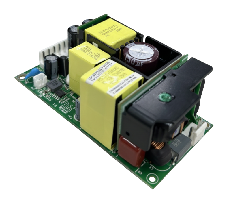
Explore the reference product and focused alternatives using Phihong manufacturer photographs. Each model requires its own configuration and documentation review.

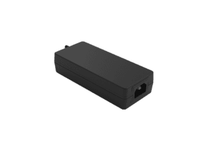
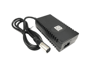
BI240-240A-R
Reference model for this article. 240W, 24V industrial supply with separately documented boost conditions.
Manufacturer photograph; some variants share a family image.

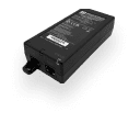
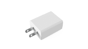
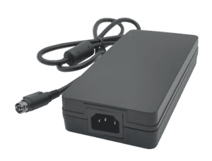
BI150-240A-R
Lower-power architecture comparison. Review the qualified machine load and installation separately.
Manufacturer photograph; some variants share a family image.
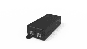
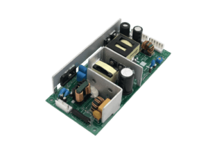
PBL300M-240
Higher nominal 24V power candidate. Apply its own cooling, mounting, connection and protection requirements.
Manufacturer photograph; some variants share a family image.
Related Product Options
The models below support a focused comparison. Regional variants and different power classes need their own documentation and final equipment review. This comparison does not establish drop-in interchangeability.
| Model | Reason to consider | What to verify |
|---|---|---|
| BI240-240A-R | Reference model for this article | 240W, 24V industrial supply with separately documented boost conditions |
| BI150-240A-R | Lower-power architecture comparison | Review the qualified machine load and installation separately |
| PBL300M-240 | Higher nominal 24V power candidate | Apply its own cooling, mounting, connection and protection requirements |
Product and OEM Resources
FAQs
Is 200% boost the same as 480W continuous power?
No. The documented boost is short-duration operation. Continuous output and repetitive average-power requirements remain separate conditions.
Does an average below 240W prove the pulse is acceptable?
It is a useful screening calculation. It does not replace peak duration, installation, input, temperature or final equipment validation.
Can an electronic load replace the final machine test?
It can provide repeatable source characterization. The actual machine and harness still need functional evaluation because their dynamic behavior may differ.
Should voltage be measured only at the supply?
Observe the supply and any sensitive receiving circuit when distribution loss could affect the result. Keep measurement locations with the traces.
What if the supply enters protection?
Treat that as a condition to investigate. Confirm the fault and documented recovery behavior before deciding whether the operating sequence is suitable.