









BLOG
Industrial Power Supply Recovery: Which Faults Clear Automatically and Which Require an AC Restart?
QUICK LINKS
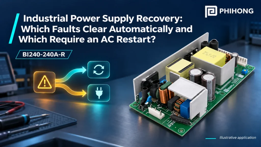
Quick answer. Two power interruptions can look identical at the machine controller yet require different recovery actions. The BI240-240A-R documentation distinguishes automatically recovering overcurrent and short-circuit behavior from latching overvoltage and overtemperature protection. An OEM should connect those component behaviors with the machine’s safe state, restart policy and functional acceptance. Restoring voltage alone does not establish that production can resume.
This guide uses BI240-240A-R and its technical datasheet as the model reference. Apply the documented conditions to the actual equipment configuration.
Why This Topic Matters Now
A machine may be modified so that a controller, drive and auxiliary load share a supply that previously served fewer functions. A fault can then interrupt several circuits at once, while each controller responds differently. Firmware may attempt a restart, retain an alarm or wait for an operator action. The component’s protection description is only one part of that sequence.
Separate the normal startup process from fault recovery. A successful power-on test does not cover automatic recovery after a short is removed, and neither result covers a latched thermal event. Use the 150W retrofit qualification framework for the wider equipment record, then apply the BI240’s own protection definitions. This approach avoids assuming that two supplies with the same output voltage will produce the same machine behavior after a fault.
| Situation | Question | Evidence |
|---|---|---|
| Normal startup | Does the intended sequence complete? | Startup timeline |
| Recoverable overload | What happens after the cause is removed? | Source and controller record |
| Latched event | What reset is specified? | Fault disposition and reset sequence |
| Return to service | Is the machine in the required state? | Functional acceptance result |
Why This Matters
- An output interruption does not identify its cause or recovery class.
- Machine readiness depends on more than the source returning to regulation.
What OEMs Should Do Now
- Classify the intended recovery cases before testing.
- Record controller, drive and supply states on a common timeline.
- 1. Define continuous demand
- 2. Capture peak and repetition
- 3. Apply installation limits
- 4. Verify equipment recovery
Conceptual workflow, not a test result or certification statement.
Read each BI240 protection mode separately
The BI240 datasheet describes overcurrent and short-circuit protection as automatically recovering after the fault condition is removed. It describes overvoltage and overtemperature protection as latch-off modes requiring AC recycling. Preserve those distinctions when writing the equipment’s test plan or service information. Do not summarize them as all faults recover automatically or all faults need a power cycle.
Protection thresholds and modes are fault-response information, not alternative normal operating ratings. A machine should not depend on repeatedly driving a supply into protection to implement its ordinary duty. Nor does a reset resolve the original cause. Have the responsible engineering team define appropriate controlled test methods and determine how an observed event is diagnosed before the equipment is returned to service.
| Protection | Documented recovery type | OEM concern |
|---|---|---|
| Overcurrent | Automatic after removal of the cause | Repeated demand and controller response |
| Short circuit | Automatic after removal of the cause | Downstream condition and restart |
| Overvoltage | Latch requiring AC recycling | Cause and affected equipment review |
| Overtemperature | Latch requiring AC recycling | Thermal cause and installation review |
Why This Matters
- A fault label should lead to its own recovery expectation.
- A successful reset does not establish that the initiating problem was corrected.
What OEMs Should Do Now
- Retain model-specific protection definitions in the test record.
- Keep normal operating limits separate from protection behavior.
Observe the system before, during and after interruption
Capture enough history to establish what changed before voltage disappeared. A controller log may record the final loss of supply after an earlier overload, temperature condition or downstream event. Align that log with suitable electrical observations so the sequence can be interpreted correctly. A fault message generated after the controller loses power may be an effect rather than the initiating event.
After the documented recovery condition is satisfied, verify the receiving circuits and application state. A controller may reboot while an actuator retains a mechanical position or another subsystem remains energized from a different source. Those interactions belong in the machine’s risk and functional review. Avoid generalizing a single subsystem’s ready indication to the entire machine, and document any intervention that the released process permits.
| Timeline stage | Observe | Interpret carefully |
|---|---|---|
| Before interruption | Load, temperature and commanded state | Potential initiating condition |
| During interruption | DC output and independent rails | Which circuits lost power |
| After restoration | Controller and actuator state | Whether the intended sequence resumed |
| Acceptance | Alarms and required intervention | Whether service criteria were met |
Why This Matters
- The first visible alarm may not be the cause.
- Different power domains can leave the equipment in an unexpected combination of states.
What OEMs Should Do Now
- Use synchronized observations that include the pre-event state.
- Define machine readiness independently of the power-good observation.
Control restart attempts and investigation boundaries
An automated controller that repeatedly retries an unresolved condition can make a fault difficult to characterize. Decide how the equipment should react to failed restart attempts and which observations must be retained. Those decisions should come from the machine’s approved requirements and responsible engineering review, not a universal retry count copied from another product.
For a thermal latch, investigate the installed duty, surrounding air, orientation and cooling conditions before treating a later restart as an acceptable fix. For an electrical fault, identify the affected branch and permitted diagnostic process. This article does not prescribe energized servicing, improvised fault injection or bypassing protection. The purpose is to connect documented component behavior with a controlled OEM validation and service workflow.
| Condition | Review before another attempt | Useful record |
|---|---|---|
| Repeated overload | Actual demand and allowed sequence | Current waveform and retry timeline |
| Thermal latch | Duty, orientation and surrounding air | Installation and temperature history |
| Downstream short | Affected assembly and disposition | Controlled investigation record |
| Uncertain cause | Evidence needed for diagnosis | Open question and owner |
Why This Matters
- Repeated resets can conceal an unresolved cause and erase useful context.
- Thermal recovery needs an installation review as well as an electrical restart observation.
What OEMs Should Do Now
- Set restart and escalation behavior through the equipment’s approved process.
- Retain the evidence required to distinguish cause from consequence.
Build a model-specific recovery record with Phihong
An actionable enquiry identifies the BI240-240A-R, hardware and document revision, measured load, input conditions, mounting and temperature observations. Include the event timeline and the exact behavior that differs from expectation. Ask which documented mode applies to that evidence. A statement that the machine sometimes turns off does not give a supplier enough information to distinguish source behavior from another part of the assembly.
Once the issue is resolved, connect the result with the production bill of materials and service procedure. The RFQ evidence checklist can help preserve a consistent procurement record, while the startup demand investigation provides context for load-related symptoms. If another supply is selected, review its recovery definitions independently. Matching voltage or wattage does not establish matching fault behavior.
| Record | Detail | Release use |
|---|---|---|
| Component identity | Model and relevant revision | Traceable supplier evidence |
| Event evidence | Waveforms, logs and conditions | Cause and behavior comparison |
| Disposition | Corrective action and retest | Engineering acceptance |
| Service process | Permitted recovery and escalation | Consistent field response |
Why This Matters
- A focused supplier question is easier to resolve than an unbounded symptom report.
- A component substitution can change the equipment’s recovery sequence.
What OEMs Should Do Now
- Send the timeline and conditions with the model-specific question.
- Update the approved recovery and service record after the issue is closed.
Key Takeaways
Keep automatic recovery and latch-off protection separate. Confirm the cause, observe the complete equipment sequence and validate functional readiness after the documented recovery action. A reset is part of the investigation and release process, not evidence that the original problem has disappeared.
Featured Products
Explore the reference product and focused alternatives using Phihong manufacturer photographs. Each model requires its own configuration and documentation review.

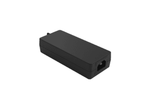
BI240-240A-R
Reference model for this article. 240W, 24V industrial supply with separately documented boost conditions.
Manufacturer photograph; some variants share a family image.

BI150-240A-R
Lower-power architecture comparison. Review the qualified machine load and installation separately.
Manufacturer photograph; some variants share a family image.
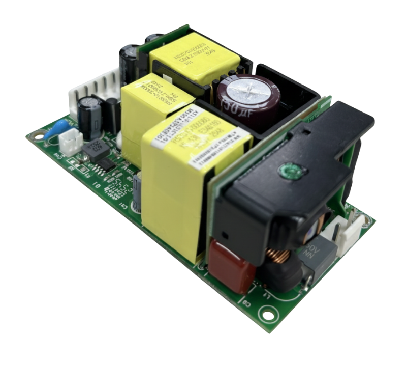
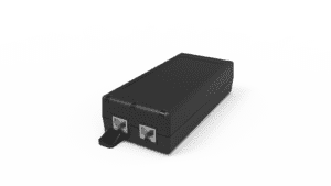
PBL300M-240
Higher nominal 24V power candidate. Apply its own cooling, mounting, connection and protection requirements.
Manufacturer photograph; some variants share a family image.
Related Product Options
The models below support a focused comparison. Regional variants and different power classes need their own documentation and final equipment review. This comparison does not establish drop-in interchangeability.
| Model | Reason to consider | What to verify |
|---|---|---|
| BI240-240A-R | Reference model for this article | 240W, 24V industrial supply with separately documented boost conditions |
| BI150-240A-R | Lower-power architecture comparison | Review the qualified machine load and installation separately |
| PBL300M-240 | Higher nominal 24V power candidate | Apply its own cooling, mounting, connection and protection requirements |
Product and OEM Resources
FAQs
Which BI240 faults recover automatically?
The documentation describes automatic recovery after overcurrent and short-circuit causes are removed. Verify the actual equipment sequence under the approved test conditions.
Which modes require AC recycling?
The documented overvoltage and overtemperature modes latch off and require the specified AC reset after the cause has been addressed.
Can protection be used as a normal duty-control mechanism?
Do not treat fault protection as an expanded normal operating envelope. Evaluate ordinary duty against the supply’s documented operating requirements.
Does a controller reboot prove the machine recovered?
No. Check the other power domains, actuators, alarms and process readiness required by the equipment’s acceptance criteria.
What information should accompany a fault enquiry?
Provide exact model and revision, waveform and controller timeline, input and load conditions, installation details and the specific observed behavior.