









BLOG
Open-Frame PSU Integration: What Changes Between 4×2 and 5×3-Inch Footprints?
QUICK LINKS

Quick Answer: Moving from a 4×2-inch to a 5×3-inch open-frame power supply changes the space reserved for the supply and may change mounting, cable routing, service access and cooling. Compare the complete installed assembly using controlled model drawings. A shared output voltage does not establish mechanical interchangeability, and the board footprint does not include every clearance an OEM enclosure needs.
An equipment upgrade often begins with a simple request: retain the existing enclosure and add more power. The supply looks like an ordinary rectangle in the first packaging drawing, so the team may assume a slightly larger rectangle is the only change. That assumption becomes expensive when a connector faces a wall, the cover obstructs airflow or a technician cannot remove the assembly.
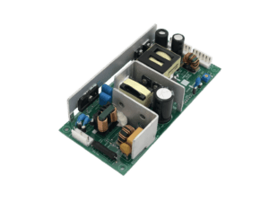
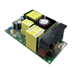
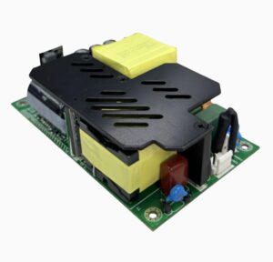
Phihong’s PBL300M documentation identifies a 4×2-inch format, while the PBL600L documentation identifies a 5×3-inch format. This article follows the mechanical questions raised by that comparison. Use the 300W and 600W selection guide for the broader load and architecture decision. Here, the goal is a buildable, serviceable installation supported by the exact candidate’s documentation.
What does the footprint tell you about the installed assembly?
A nominal footprint is useful for screening available space. It does not describe every object around the power supply or define the equipment’s electrical clearances. The 4×2-inch and 5×3-inch labels should therefore begin a packaging review rather than finish it. Check the current model document before converting a family description into a released CAD requirement.
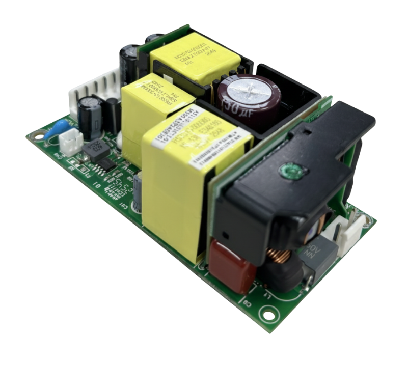
The PBL300M datasheet lists a 4×2×1.5-inch dimensional reference. The PBL600L datasheet lists 5×3×1.64 inches. These references distinguish the families, but they do not supply a universal mounting pattern or a ready-made clearance rule for your enclosure. Request the controlled drawing for the actual model and assembly being evaluated.
Create separate entries for the supply envelope, mating parts, cable movement and surrounding hardware. This prevents a mechanical drawing from quietly absorbing electrical or assembly assumptions. If the equipment team has only a marketing image, label the installation provisional. Do not derive a hole pattern by scaling the photograph or assume that a connector remains accessible because the bare board fits.
Why This Matters
- A nominal board size describes less than the complete installed configuration.
- A controlled drawing lets mechanical, electrical and sourcing teams discuss the same candidate.
What OEMs Should Do Now
- Request the current model drawing and identify which dimensions belong to the supplied assembly.
- Keep unresolved mounting and clearance questions visible before freezing the enclosure.
FEATURED PRODUCTS

PBL300M-120
- Output Power - 300W(with Fan)
- Output Volt - 12Vdc
- Features - Class I Design , High Efficiency Performance , OVP, OCP, SCP, OTP Protections , Operating Altitude: 5,000M
PBL300M-240
- Output Power - 300W(with Fan)
- Output Volt - 24Vdc
- Features - Class I Design , High Efficiency Performance , OVP, OCP, SCP, OTP Protections , Operating Altitude: 5,000M

PBL600L-240
- Output Power - 600W(with Fan)
- Output Volt - 24Vdc
- Features - Class I Design , High Efficiency Performance , OVP, OCP, SCP, OTP Protections , Operating Altitude: 5,000M
PBL600L-480
- Output Power - 600W(with Fan)
- Output Volt - 48Vdc
- Features - Class I Design , High Efficiency Performance , OVP, OCP, SCP, OTP Protections , Operating Altitude: 5,000M

How should OEMs review height and neighboring components?
Height is a system question. A component may clear the enclosure cover while still obstructing a wire path or leaving insufficient access for assembly. Review the supply with the intended standoffs, chassis features, brackets and cover installed. Include the nearby equipment that will actually occupy the space, rather than checking the supply in an otherwise empty enclosure.
The published dimensional reference does not establish the separation required from every neighboring surface. Ask the equipment’s responsible engineer to determine the applicable installation and safety requirements using the supplier’s documentation. A compact layout is not evidence that electrical separation, protective measures or thermal requirements have been met. Keep each requirement connected to its source and owner.
Check the assembly sequence as well as the final position. A board that can be placed in an empty chassis may be impossible to install after a neighboring module is fitted. Conversely, a practical sequence might remove an apparent conflict without changing the enclosure. Record the proposed sequence and verify it on representative hardware. Include tolerances and the supplied configuration in the review instead of treating one hand-built fit check as the complete production answer.
| Review area | Evidence to retain | Question to close |
|---|---|---|
| Vertical space | Drawing and installed stack | What occupies the space above and below the supply? |
| Adjacent parts | Representative enclosure assembly | Do covers or brackets change access or cooling? |
| Assembly sequence | Build and removal trial | Can the supply be installed and serviced in sequence? |
Why This Matters
- The usable space includes the installed stack and nearby hardware.
- A successful static fit does not prove that the assembly process is practical.
What OEMs Should Do Now
- Review the supply inside the representative equipment assembly with its actual supporting hardware.
- Document the intended installation and removal sequence before approving the packaging layout.
Why do connector orientation and cable access change the result?
Start the connection review with the exact candidate’s terminal arrangement and specified mating parts. Do not assume that a larger power class uses the same connections as the existing board. A nominally identical output voltage says nothing about whether a connector can be reached, routed or disconnected within the proposed equipment.
Reserve the path used during assembly and service. A cable may need room to approach its termination, a tool may need access and the finished harness may need support away from other parts. Obtain the applicable installation information rather than inventing a universal bend allowance or terminal rating. Verify the actual wire and connector combination chosen for the equipment.
A larger footprint can move a connection closer to an enclosure wall even when the board remains inside the original mounting area. It can also change how the harness passes nearby components. Review the routing with both electrical and mechanical owners. If the upgrade also changes the load, assess the current path separately; extra enclosure space does not qualify the existing harness for a new operating requirement.
The broader open-frame and enclosed comparison can help when the architecture itself remains open. Once an open-frame candidate is selected, retain a connection drawing that shows the installed routing and service access.
Why This Matters
- Connection access can govern integration even when the supply outline fits.
- A changed harness or connection arrangement requires its own equipment review.
What OEMs Should Do Now
- Confirm the candidate’s released connection information and proposed mating parts.
- Trial the installed harness and service access with the enclosure and adjacent hardware present.
How can a footprint change disturb the enclosure cooling path?
A packaging change can change the air path. The supply may sit closer to a wall, a harness may cross an inlet area or a new bracket may redirect flow. These changes matter even if the equipment retains the same fan. A fan’s presence does not establish the local cooling conditions required by the candidate supply.
The PBL300M and PBL600L documents distinguish convection and forced-cooling operation. Read the conditions for the exact model and intended load. Do not transfer the cooling assumptions from the old supply to the new one merely because both are open-frame products. If required airflow or installation conditions are unclear, ask Phihong before accepting the layout.
Evaluate the representative enclosure rather than relying on an open-bench temperature check. Use the operating combinations that create the relevant equipment demand and retain the mounting, orientation, cover and airflow configuration with the results. Phihong’s enclosure thermal validation guide provides related background, but the new candidate still needs its own documented review.
Keep mechanical and thermal changes connected in the release record. If a vent, filter, bracket or neighboring module changes after testing, identify which results remain representative. An apparently small packaging revision should not disappear from the evaluation history simply because the nominal supply wattage stayed the same.
Why This Matters
- A new board position can change local cooling without changing the installed fan.
- Thermal evidence applies to a defined equipment configuration.
What OEMs Should Do Now
- Confirm the exact model’s cooling basis and unresolved installation conditions with Phihong.
- Evaluate the intended enclosure with its actual covers, routing and neighboring equipment.
What should a mechanical integration approval include?
Make the approval record specific enough that another engineer can identify what was evaluated. Include the supply model, drawing revision, equipment revision, supporting hardware, harness configuration and relevant test conditions. Distinguish accepted evidence from a planned check. A single approved label should not hide an unresolved connector, drawing or cooling question.
Use a short change review when comparing the old and proposed supplies. Identify which dimensions, mounting features, connections and operating conditions changed, then assign the required checks. Some earlier equipment evidence may remain useful, but that is a reasoned decision rather than an automatic consequence of retaining the same enclosure.
Ask assembly and service staff to review the practical installation. Their observations can reveal inaccessible fasteners, awkward harness routing or removal sequences that were easy to miss in CAD. Record the configuration they used so later production changes can be compared against it. Resolve conflicting assumptions before the bill of materials and enclosure drawings are released.
Phihong can review the candidate model and documentation with your team when you provide the equipment requirement. Use the internal PSU product range to identify candidates, then request the current drawing and installation information. Confirm sample configuration and availability directly rather than treating a product listing as a delivery commitment.
Why This Matters
- A traceable configuration makes later substitutions and enclosure changes easier to assess.
- A cross-functional review catches installation problems that a board outline can miss.
What OEMs Should Do Now
- Retain a model-specific integration checklist with evidence and named owners for open questions.
- Review assembly, service and cooling changes before releasing the updated equipment configuration.
Frequently Asked Questions
Can a 5×3-inch power supply replace a 4×2-inch model if the voltage is the same?
Possibly, but the common voltage does not establish interchangeability. Compare the exact output requirement, physical envelope, mounting, connections, cooling and equipment behavior. Identify which earlier evidence remains representative and which checks must be repeated. Treat the substitution as an equipment change review rather than a direct replacement based only on the voltage label.
Does the footprint include space for the mating connectors and cables?
Do not assume that it does. Use the controlled model drawing to identify the supplied assembly envelope and obtain the applicable connection and installation information. Reserve additional access and routing space according to the actual equipment design. Verify the installed combination, including the selected mating parts and the assembly or removal path.
Can OEMs use a product photograph to create the mounting pattern?
A photograph is useful for orientation, but it is not a controlled mechanical drawing. Perspective, image scaling and assembly variation can make inferred dimensions unreliable. Request the exact model’s drawing and confirm the proposed mounting arrangement. Keep a fit check provisional while essential mounting information remains unresolved.
Will a larger footprint always improve cooling?
No. Cooling depends on the specific design and installation. A larger supply may change its proximity to walls, cables and neighboring hardware. Review the applicable convection or forced-cooling basis, then evaluate the representative enclosure at the intended operating conditions. Do not infer a thermal advantage from board size alone.
What should we send Phihong for a packaging review?
Send the exact candidate model, available envelope, equipment load, required output, proposed mounting and cooling arrangement. Include a connection or enclosure drawing where appropriate and identify the missing information that controls the decision. Ask for the current model drawing and supplied sample configuration so the discussion addresses the installation being evaluated.