









BLOG
5V Load Budget: Which Accessory Functions Can Push a Device Past 1A?
QUICK LINKS

A 5V accessory can move from a quiet standby state to concurrent battery charging, display activity and wireless transmission within one operating sequence. If the design spreadsheet contains average current only, the combination that actually stresses a 1A source may be absent from the record. The useful budget shows what happens together and when.
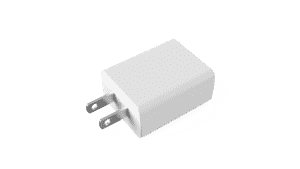
Quick answer. Measure the total current at the accessory input while marking transitions such as charging enable, display wake and radio activity. Compare the measured current and device-side voltage with the exact source and accessory requirements. Phihong rates the MQ05A-050BW-H at 5V and 1A. Use the B-series datasheet for model details.
Why This Topic Matters Now
Low-power platforms often add functions without changing the enclosure or external power specification. A brighter display or revised radio firmware can alter peak overlap even when standby and average current remain acceptable. An accessory can also behave differently when its battery charge state, health or temperature changes within the intended operating range.
Start with an event matrix rather than an aggregate current estimate. Identify which functions can run together, what firmware controls the sequence and which modes the battery can support.
Which functions can create the highest combined demand?
Display brightness, radio transmission and battery charging are common candidates. Sensor warmup, storage writes or a downstream converter starting can also add brief demand. Trace the signals that mark those events, then compare their timing with input current. Internal branch currents are useful for diagnosis if their voltages and conversion paths are identified.
| Function | Current evidence to capture |
|---|---|
| Battery charging | Charge condition and input behavior as the charge stage changes |
| Display or backlight | Turn-on event and steady current at approved brightness levels |
| Wireless interface | Association, transmit activity and any retry patterns |
| Sensor or storage | Startup, measurement or write events that overlap other loads |
An example accessory might draw 0.44A at a 5V input before a display and radio event. If the measured event adds 0.35A and a coincident charging change adds 0.26A, the illustrative total is 1.05A. That example describes an arithmetic screening case. Actual transitions can interact and should be measured at the input rather than assumed additive.
How do you measure without hiding short events?
Use a qualified measurement setup with enough time resolution to capture the relevant pulse. A meter that averages over a longer interval can report an acceptable value while missing a short event. Record duration and repetition along with the peak, and capture device input voltage at the same time. If the measurement setup adds meaningful voltage drop, document it and account for it.
Test with the released cable and firmware. Where a battery is involved, document charge state and whether it can contribute during the event. An accessory that is stable with a full battery may follow a different power path when the battery is depleted. Use the applicable conditions approved for the product’s battery and equipment.
Which changes are worth testing first?
Compare the branches individually and together. If simultaneous events create the problem, one candidate correction is to change timing or limit a noncritical function during the event. Another is to qualify a source and cable combination that supports the actual load requirements. Both choices can affect other parts of the design.
| Candidate change | Follow-up evidence |
|---|---|
| Delay display wake | Verify readiness and user interaction timing |
| Change charge policy | Verify charging behavior, device state and recovery |
| Improve the cable path | Check approved part control and field availability |
| Select a different source | Repeat source detection, safety review and system qualification |
A symptom that disappears after a firmware change still deserves a documented explanation. Keep the original failure trace, corrected trace, test conditions and the exact firmware build in the design file.
What does a useful load-budget worksheet contain?
Record each operating state, concurrent functions, source and cable, measured current, minimum device voltage, duration and pass criteria. Add the trace reference and test operator or owner. Keep operating state labels consistent between the electrical test record and firmware logs. That makes comparison possible when a later revision adds a function or changes the wake sequence.
Include states that represent intended use and the boundary conditions defined by the product team. An average budget still helps estimate ordinary consumption. A separate event budget addresses the behavior that can make an accessory reset or change its operating state.
Key Takeaways
Compare measured accessory input with the source rating and the accessory’s voltage requirements. Use event timing to separate simultaneous demand from cable loss and downstream behavior. Release the exact hardware and firmware configuration represented by the evidence.
FAQs
Can a brief peak above 1A be ignored?
No general duration is safe to assume. Compare the observed current and voltage with the source’s documented behavior and the product’s approved requirements.
Is averaging helpful?
It helps describe typical consumption. Use time-resolved measurements for startup, transitions and brief overlaps.
Do the power readings from different internal rails add as current?
Compare them on a common power basis or measure at the accessory input. Different rail voltages and conversion losses make direct current addition misleading.
Discuss your design with Phihong. Review the medical usb power product family or contact Phihong with the model, operating conditions and qualification question.