









BLOG
Medical USB Power: When Is a 5W, 5V Adapter Enough for a Low-Power Accessory?
QUICK LINKS
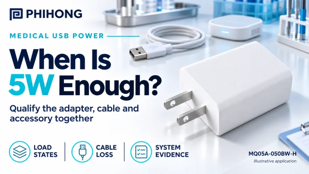
A low-power accessory can draw less than 5W during ordinary operation and still fail when it starts with a depleted battery, turns on its display or begins a wireless exchange. Qualifying an adapter means checking the complete power path, including source behavior, the actual cable and the accessory’s requirements at its own input.
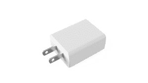
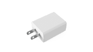
Quick answer. A 5W adapter is a candidate when the accessory fits within the permitted source current and its input stays within the required voltage window across intended use, cable options and recovery conditions. Phihong identifies the MQ05A-050BW-H as a single-port 5V, 1A USB-A medical adapter for the US configuration. Evaluate the exact B-series datasheet alongside the complete equipment requirements.
Why This Topic Matters Now
A display, radio or battery can be added to an accessory while the external adapter stays on the original purchase list. The labels may still look compatible. The power path may now have less margin during a simultaneous event, or the firmware may assume a charging source that the field kit does not contain. The relevant question is what the shipped combination can support throughout the intended sequence.
Use this guide for the OEM’s design and verification file. Start with the actual use case, then decide which states, cables and source combinations the product will support. An engineering sample connected through a short bench cable can demonstrate function without covering what a field user sees.
| Design input | Why it matters |
|---|---|
| Intended role of accessory | Establishes which functions must be sustained and which operating limits apply |
| Exact adapter and cable | Defines connector, identification behavior, region and distribution loss |
| Electrical operating states | Captures charging, display, radio, startup and recovery |
| Safety and EMC evidence | Identifies component documents and final equipment evidence |
| Service replacements | Defines what can be shipped and how alternatives are qualified |
Which operating states should go into the load budget?
Measure at the accessory input and separate ordinary consumption from state transitions. Include standby, boot, active measurement or logging, display brightness changes, wireless activity and battery charging where present. State whether those functions can occur together. If a product requirement deliberately prevents overlap, test the requirement with the released firmware and verify the behavior in relevant recovery states.
| State | What to record |
|---|---|
| Off or standby | Idle consumption and restart trigger |
| Initial boot | Input current, input voltage and time to application ready |
| Charging | Battery condition, charge behavior and concurrent functions |
| Active operation | Display, sensor and radio behavior in the intended mode |
| Recovery | Reconnection behavior and product state after an interruption |
A current reading at an internal 3.3V rail does not equal current at the 5V input. Where branch measurements are used to explain the load, reconcile them with measured accessory input and the conversion path. Battery-assisted behavior deserves its own row. The accessory may appear to run normally on one battery state and perform differently when a battery cannot supply the same support.
How does the cable change available voltage?
The 5V nameplate applies to the source’s rated output. The accessory receives power through contacts, conductors and an input circuit. The device-side voltage can fall when current rises, especially with longer paths or higher resistance. Measure source voltage and accessory input voltage during the same event and retain the approved cable part number with the traces.
| Check | Decision supported |
|---|---|
| Approved short and long cables, where offered | Whether all shipped variants meet the same requirement |
| Source and device input measured together | Whether a dip originates at the adapter or develops in the cable path |
| Different samples and repeat runs | Whether the result is reproducible across production conditions |
| Reconnection | Whether connector engagement and firmware restore normal function |
Record the minimum input voltage that the accessory actually requires and the allowed duration of any excursion. That limit should come from the design requirements and affected functions. The adapter datasheet specifies a particular ripple test arrangement. Follow the applicable documented conditions for a supplier comparison and keep that test distinct from the accessory’s actual operating measurement.
When does USB-A suit the accessory and its service network?
USB-A can be practical where the installed base, approved cables and replacement kits already use it. The MQ05A-050BW-H documentation identifies shorted data pins for this exact model. The device’s input policy determines how it interprets the source. Document how the accessory detects the connection and chooses an input limit, then confirm that behavior with the actual cable and approved accessory firmware.
USB-C may be the right path for a new design with different interoperability needs. The connector alone does not specify the operating voltage, negotiated power or compatible set of cables. A transition from USB-A should be treated as a change to the approved source, sink and cable combination. Where both are offered, document the combinations separately and route unapproved ones through engineering review.
What belongs in the system qualification file?
Keep the exact adapter and cable part numbers, supplier documents, relevant certifications and restrictions, device-side voltage and current evidence and a reviewed list of permitted configurations. Component documentation contributes to the system file. The OEM’s compliance and risk teams determine the evidence required for the finished configuration and intended use.
| Record | Owner and purpose |
|---|---|
| Released accessory BOM | Identifies the approved device, adapter, cable and regions |
| Electrical traces and state matrix | Establishes what was tested and which limits applied |
| Component documentation | Ties supplier evidence to the precise part and revision |
| System test disposition | Records the responsible team’s decision for the complete configuration |
| Service controls | Keeps field replacements within the approved combination |
For a finished medical electrical product, use the applicable standards and system assessment determined by the compliance team. The IEC 60601-1 overview describes the standard’s general equipment safety and essential performance scope. The component’s MOOP classification describes documented operator protection for the component. The end product’s safety evidence needs to address its own intended use and architecture.
How should service replacements preserve the approved combination?
The kitting record should name the exact adapter, cable, region and accessory variant. Add a clear method to identify the part in the warehouse and at the service bench. Keep purchase specifications, work instructions and field notices synchronized. If a supplier updates a model or part suffix, route the proposed change through the owner of the qualification evidence.
Review field returns using the same matrix. Ask which adapter and cable were present, what the accessory was doing and whether the battery was low. Match the combination to the approved list and preserve the original components with the return where practical. Otherwise a reproducible field problem can disappear when the lab changes the cable or source during intake.
Key Takeaways
Use the nominal 5W rating to screen a candidate, then qualify the accessory at its own input. Verify overlapping functions, cable loss, source detection and recovery with the shipped configuration. Carry the exact adapter and cable into the service and compliance records.
FAQs
Can a 5V, 1A adapter power every accessory labeled 5V?
Suitability depends on current demand, voltage at the accessory, input policy, cable and intended operating modes.
Should battery charging be included in accessory consumption?
Include it when charging can occur during operation. Measure at the accessory input and record the conditions that produce the highest relevant combined demand.
Can a component medical rating replace the system assessment?
Use the component documentation as input to the applicable assessment. The complete product and its approved configurations require their own evidence and disposition.
Should OEMs verify all service cables?
Verify each supported cable or document how the qualification covers the permitted variations and limits.
Discuss your design with Phihong. Review the medical usb power product family or contact Phihong with the model, operating conditions and qualification question.