









BLOG
USB-C Power Delivery: How Does Cable Resistance Affect 65W Power at the Device?
QUICK LINKS

Quick Answer: Cable resistance can create voltage drop and resistive loss between a USB-C source and the receiving device. Review the cable, operating current and measurement boundary before interpreting a 65W claim. Phihong’s AQ65R datasheet defines output testing at the end of a specified reference cable, so do not automatically subtract an estimated cable loss from a value that already uses a device-side measurement point.
An adapter can perform as expected in the laboratory while equipment behaves differently with another cable. The replacement may look similar and have the same nominal length, yet the evaluation no longer represents the released combination. A useful OEM review identifies which cable and connection conditions the evidence actually covers.
The AQ65R-59FKA-R product record provides a relevant 65W interchangeable GaN candidate. This article focuses on cable identity, resistance and the location of the power measurement. It does not treat a matching USB-C shape as proof that two cables are equivalent.
For the complete equipment review, see the 65W OEM qualification guide.
Where is the output performance being measured?
Start by identifying the measurement boundary. The AQ65R datasheet specifies output-parameter testing at the end of a 2-meter Type-C cable described as 130mΩ. Retain that reference condition with the specification. It is more informative than quoting a power or voltage figure without showing where it applies.
A measurement at the source connector and a measurement after the installed cable do not describe the same point. Before calculating an additional voltage drop, determine whether the cited performance already includes a cable. Otherwise, a review can count an assumed loss twice and draw an unsupported conclusion about the available device power.
Do not assume that the reference cable describes every permitted equipment cable. Its length alone is not a complete replacement specification, and a resistance statement needs a clearly defined measurement path. Ask Phihong to clarify any condition needed to relate the reference setup to the actual connection being evaluated.
Retain the source document revision and the equipment cable identity together. When comparing a supplier result with a laboratory observation, show both measurement locations and operating conditions. This makes an apparent disagreement easier to investigate without assigning the difference prematurely to the adapter.
Why This Matters
- The measurement point determines whether a stated result already includes a cable path.
- A reference setup is not a blanket statement about every replacement cable.
What OEMs Should Do Now
- Label source-side and device-side observations with their exact measurement locations.
- Confirm the reference cable condition and any unclear resistance definition with Phihong.
FEATURED PRODUCTS

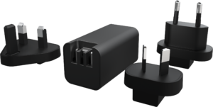
AQ65R-59FKA-R
- Output Power - 65W
- Output Volt - 5V/9V/15V/20V
- Output Current - 3A/3A/3A/3.25A
- # of ports - 1
- Features - GaN Technology, Interchangeable USB Type-C ,DoE Level VI Compliance, 5,000 Meters Operating Altitude, Suitable for commercial and consumer electronic products
- Note: Clips are sold separately
How do current and resistance change the illustrative voltage drop?
For a simplified resistive power path, voltage drop is current multiplied by total path resistance, and dissipation is current squared multiplied by that resistance. These relationships explain why the installed current and connection path matter. They do not establish a cable’s permissible current or a USB-C compliance limit.
Consider an illustrative 3A current through a defined 0.10Ω total resistive path. The calculated drop is 0.30V and dissipation is 0.90W. Doubling that path resistance to 0.20Ω at the same current gives 0.60V and 1.80W. These examples are arithmetic only; they are not AQ65R specifications, cable acceptance limits or measurements of the datasheet’s reference cable.
Use the calculation to identify a condition worth measuring, then evaluate the actual equipment. The receiving circuit’s allowed input behavior and the established power arrangement determine what is acceptable. Do not turn a convenient estimate into evidence that an unspecified device will remain stable.
Keep the complete path clear in the record. If a resistance estimate refers to only part of the loop or excludes a connection, it should not be presented as the total installed path. Retain the assumptions with the result so another engineer can reproduce and assess the comparison.
| Illustrative total path resistance | Current | Calculated drop | Calculated dissipation |
|---|---|---|---|
| 0.10Ω | 3A | 0.30V | 0.90W |
| 0.20Ω | 3A | 0.60V | 1.80W |
| Interpretation | Examples only | Not an acceptance limit | Not AQ65R reference-cable data |
Why This Matters
- Resistance and operating current together govern the simplified drop and loss estimate.
- An estimate is useful only when its path definition and assumptions remain visible.
What OEMs Should Do Now
- Define the complete resistance path before using screening calculations.
- Check the actual device-side behavior against the equipment’s acceptance criteria.
Why must cable capability and the power profile be reviewed together?
The adapter’s maximum nominal wattage does not describe every operating profile. AQ65R lists 5V, 9V, 15V and 20V options with their respective currents. Confirm which arrangement the receiving equipment requires and which arrangement is actually established with the selected connection. A cable review that ignores the operating profile is incomplete.
Identify the cable’s relevant power and connection documentation. Mechanical mating does not establish that the combination supports the intended arrangement. The USB-IF Power Delivery overview provides general background, but it does not qualify a particular cable, adapter and receiving device as a complete equipment package.
Retain the cable identity used for the representative test. An unidentified cable can make a successful result difficult to reproduce, and a later substitution can leave the release evidence ambiguous. Include the permitted cable configurations in the equipment record instead of using a broad instruction such as any USB-C cable.
For terminology, the existing output-profile guide explains related concepts. Model-specific optional features still need confirmation. Do not infer a capability for AQ65R or a replacement cable from a general article about USB-C power.
Why This Matters
- A cable’s role needs to be assessed in the actual adapter and device arrangement.
- A nominal wattage description does not identify every condition of the equipment power path.
What OEMs Should Do Now
- Retain the established operating profile and selected cable documentation with the test record.
- Define which cable configurations the released equipment package permits.
Which equipment operating cases reveal a cable-related problem?
Use the receiving device’s operating requirements to choose evaluation cases. A monitor may have different demand with its intended functions active, while a networking device may change demand during startup or accessory use. Define the relevant combinations instead of treating a quiet idle result as representative of the entire product.
Observe the device-side input behavior at the defined measurement point. Retain the adapter, cable, device revision, established profile and operating event with the result. A source-side reading alone may not explain what reached the receiving circuit through the installed path.
Keep causes separate from symptoms. An unexpected reset or unavailable display does not prove excessive cable resistance. The adapter, connection, receiving circuit and software can affect the observed behavior. Use repeatable observations to determine where the sequence differs from the requirement before assigning a root cause.
When a cable changes, use a controlled comparison with the remaining configuration identified. If several parts change together, record that limitation rather than claiming the cable caused the difference. The goal is evidence that supports an equipment decision and a focused supplier discussion.
Why This Matters
- Idle operation can miss the equipment cases that govern the power-path review.
- A device symptom needs supporting observations before its cause is assigned.
What OEMs Should Do Now
- Evaluate the operating combinations that determine the receiving device’s power requirement.
- Retain a repeatable configuration and distinguish cable observations from unconfirmed causes.
How should cable substitutions be managed after qualification?
Treat the approved cable as part of the equipment configuration. Retain its identity and the evidence connecting it to the adapter and receiving device. If more than one cable is permitted, identify the combinations covered by the release review and the basis for any equivalence decision.
A service replacement or purchasing substitution should be assessed against the same requirement. Similar appearance, length or packaging language does not establish the same installed result. Determine whether earlier evidence remains representative and record the reason. Assign any additional evaluation needed before the changed combination is released.
Keep the supplier reference condition separate from the OEM’s approved configuration. The AQ65R datasheet’s defined cable setup helps interpret the supplier’s parameters; the equipment team still needs evidence for the cable and device it intends to ship. Ask Phihong to clarify any missing model-specific condition rather than silently broadening the reference statement.
Provide a concise comparison when requesting support: exact adapter, old and proposed cable, device revision, operating profile, measurement locations and observed behavior. That information gives the supplier a concrete technical question and helps procurement avoid substituting against an incomplete description.
Why This Matters
- A cable change can alter the equipment combination supported by the original evidence.
- Clear part and test records make purchasing and service decisions easier to assess.
What OEMs Should Do Now
- Review substitutions against the approved equipment requirement and retain the rationale.
- Send model, cable and device-side evidence when asking Phihong about an observed difference.
Frequently Asked Questions
Does the AQ65R reference cable mean any 2-meter cable will work?
No. The datasheet describes a defined measurement arrangement, including a resistance reference. Length alone is not a complete cable specification. Identify the cable selected for the equipment and evaluate the actual adapter, connection and receiving-device combination against its intended operating requirements.
Should I subtract estimated cable loss from the published 65W value?
First establish the measurement boundary and conditions associated with the published statement. AQ65R output testing uses a specified cable endpoint. Subtracting another assumed loss without understanding that boundary can count a cable effect twice. Ask Phihong to clarify the relevant condition where it controls the equipment decision.
Are the 0.10Ω and 0.20Ω examples cable limits?
No. They are illustrative total-path resistance values used to demonstrate voltage-drop and dissipation arithmetic at 3A. They are not AQ65R specifications, USB-C compliance thresholds or measurements of the datasheet’s reference cable. The actual equipment and selected cable need their own applicable documentation and evidence.
Does a device reset prove the cable has too much resistance?
No. A reset is an observed equipment symptom. Retain the established profile, device-side input behavior, operating event and complete configuration before assigning a cause. The adapter, connections, receiving circuit and software can also affect the sequence, so use a controlled comparison rather than a conclusion from one symptom.
What should be retained when approving a replacement cable?
Keep the cable identity, relevant supporting documentation, adapter model, receiving-device revision and evaluated operating arrangement. State which earlier results remain representative and why. Record any additional evaluation required so the replacement decision can be assessed by engineering, procurement and service teams.